Rev 2 v3 Print Session — Assembly Photos and Next Steps
Overnight print of the latest base plate v3 (with support blocks and raised battery rails), updated cradle insert, and top cover. All three parts fit-checked with the Pico 2 W, TP4056 charge board, Ansmann AAA Li-Ion batteries, and Waveshare 2.13" e-ink display. Also pictured: a small solar panel being evaluated for future charging.
What changed since last print
- Base plate v3: Battery rails raised 5 mm (now extend 2 mm above the plate top for better battery retention). Two 5x15 mm support blocks centered on the USB-C axis brace the TP4056 board from below. Pico retention block added.
- Cradle insert: Battery bay position and Pico nest length refined from yesterday's iterative session.
- Top cover: 5 mm wall extension below the mating plane for deeper engagement with the base plate.
Full exploded layout
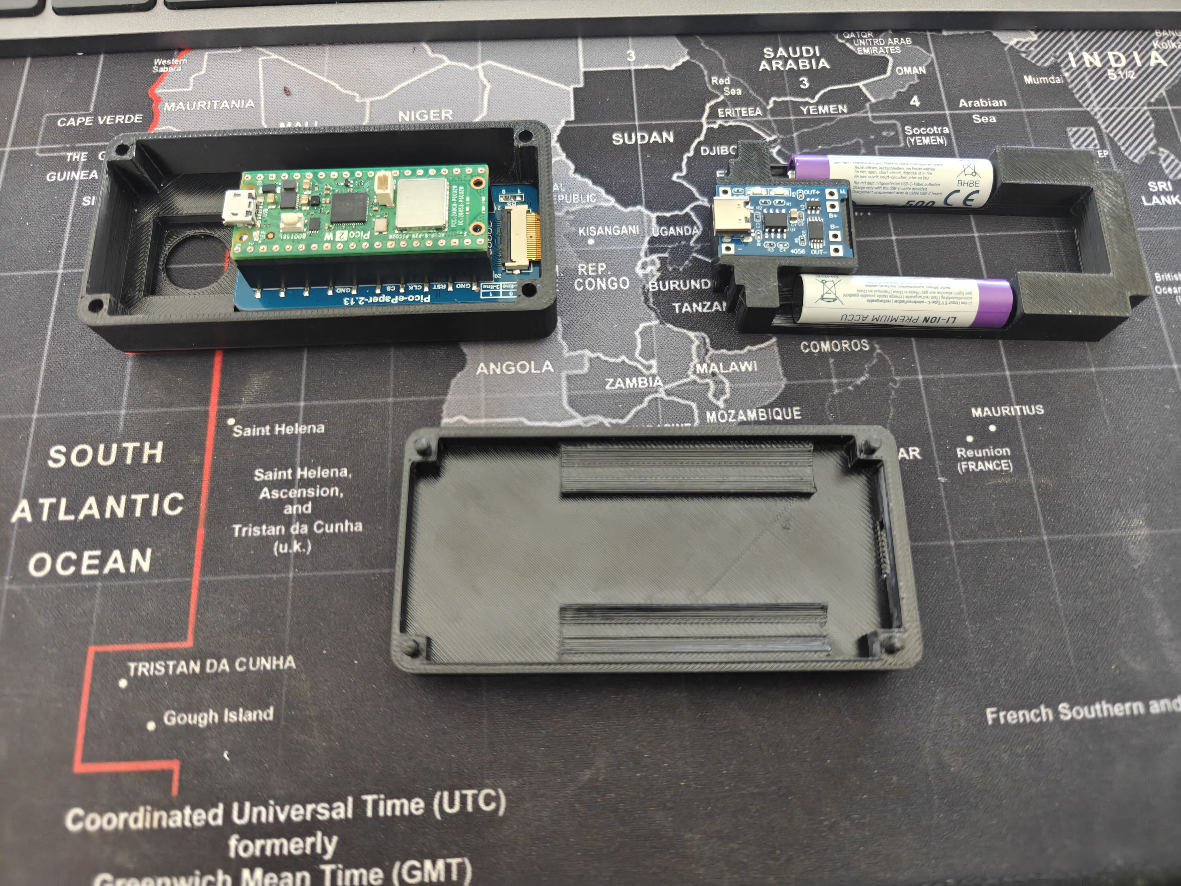
All three parts laid out with components: top cover (Pico 2 W + Waveshare display), cradle (TP4056 + AAA batteries), and base plate.
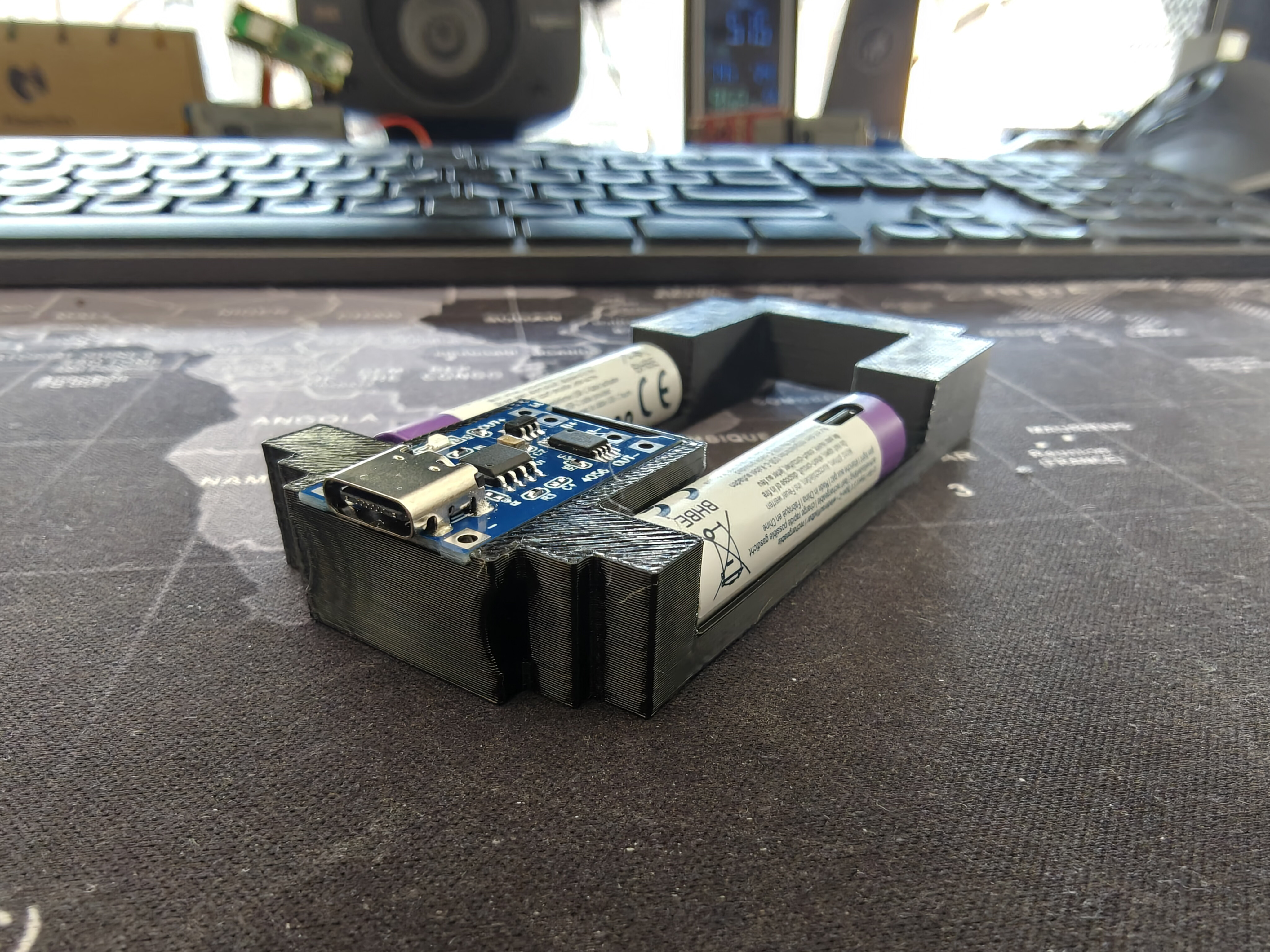
Cradle insert — fully loaded
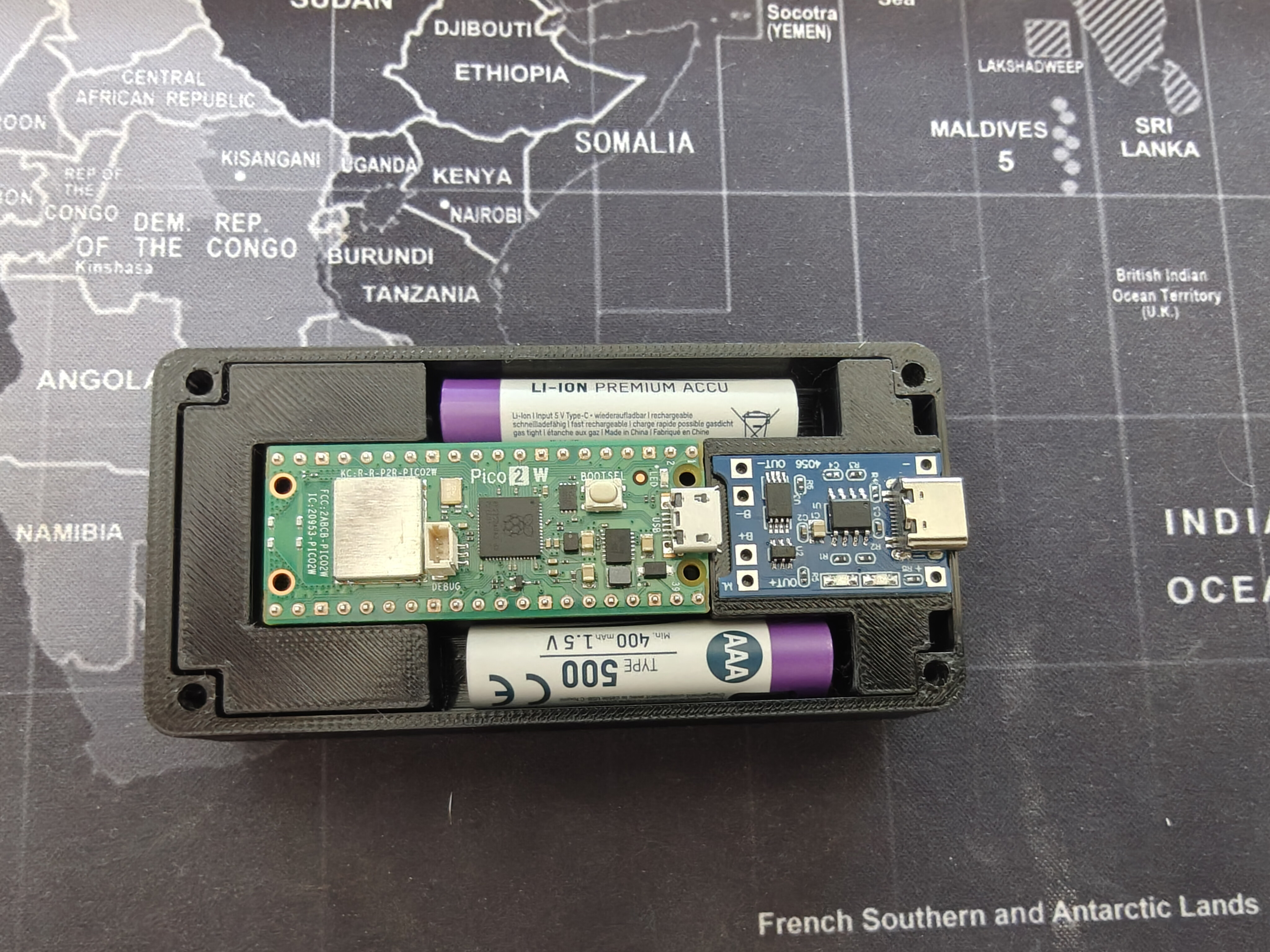
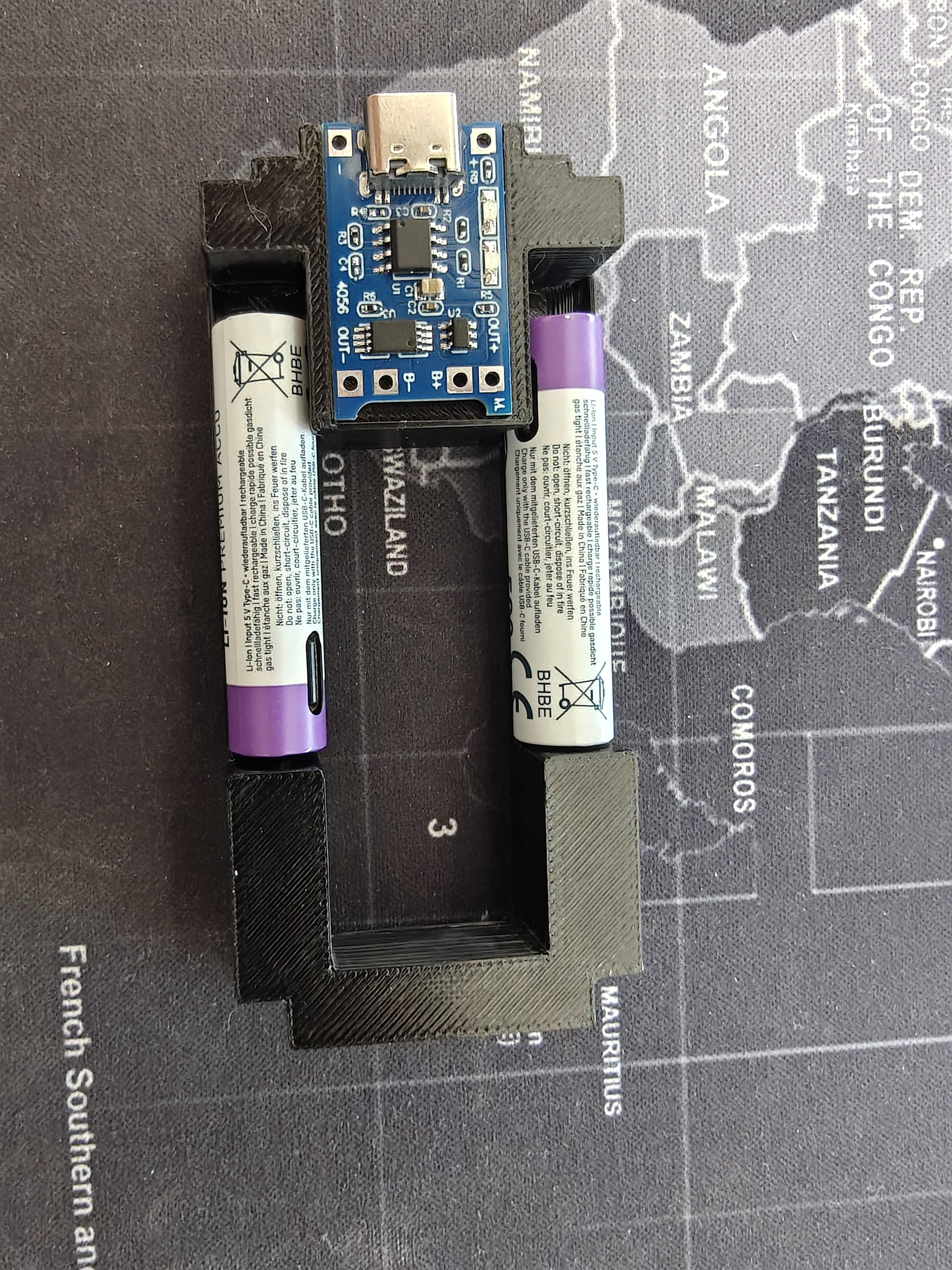
Pico 2 W in the center nest, TP4056 charge board at the +X end, two Ansmann 1.5V Li-Ion AAA batteries in the flanking bays. The connecting block positions the TP4056 with its USB-C port aligned to the +X wall cutout.
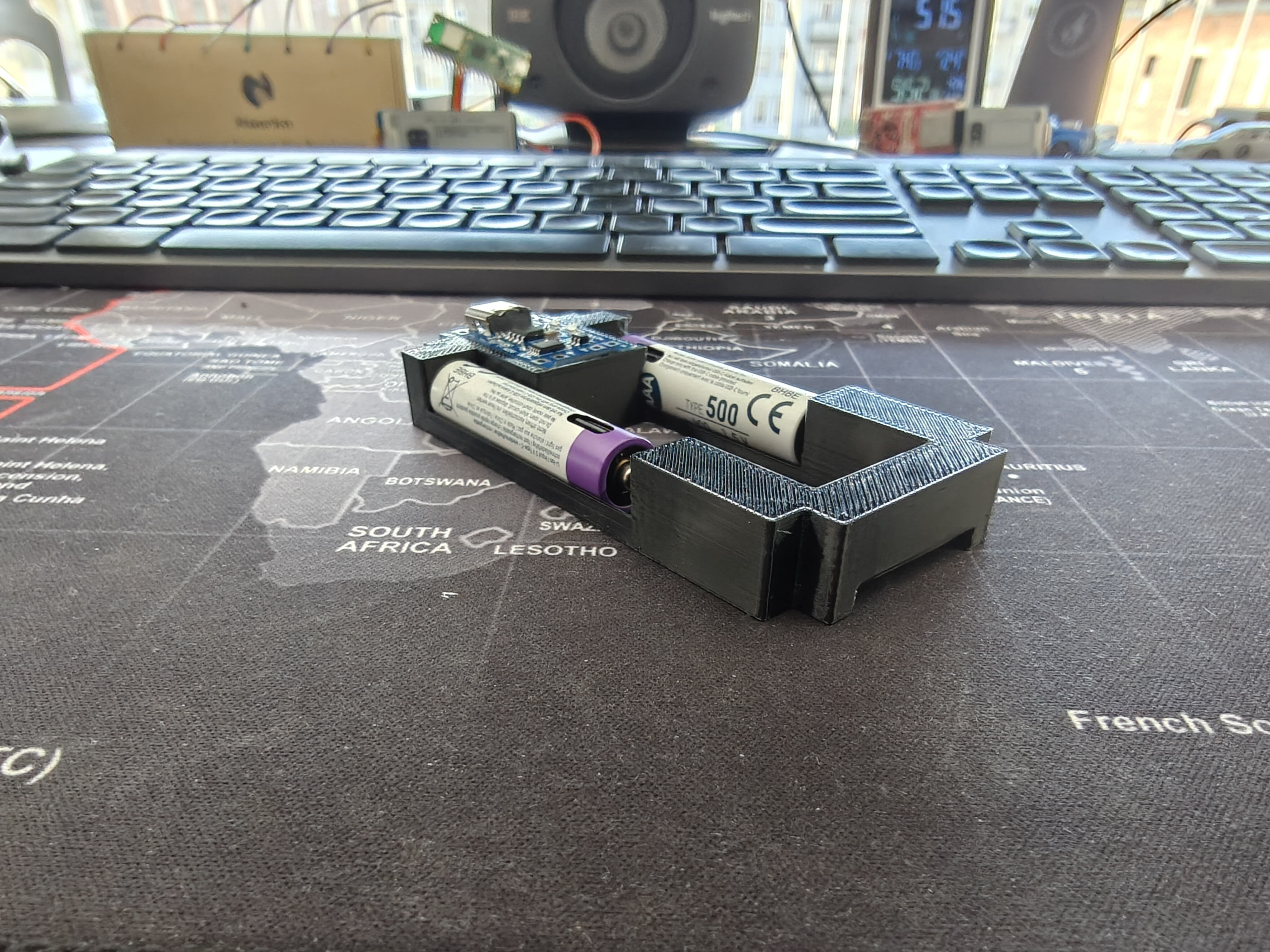
Side and angled views
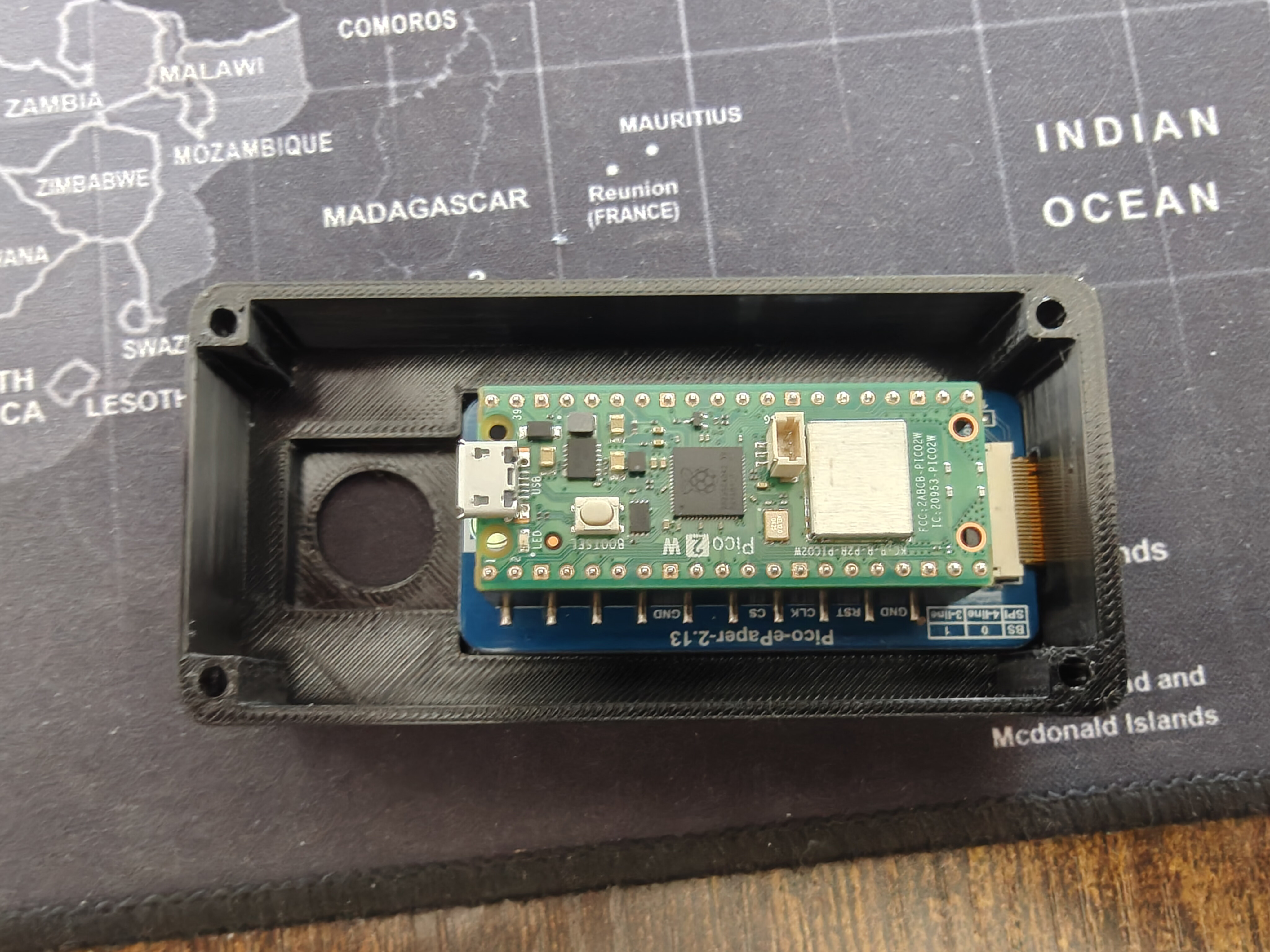
Top cover interior
The Pico 2 W board seated in the cover's nest, with the Waveshare FPC ribbon cable folded over. The joystick through-hole and display inlay recess are visible.
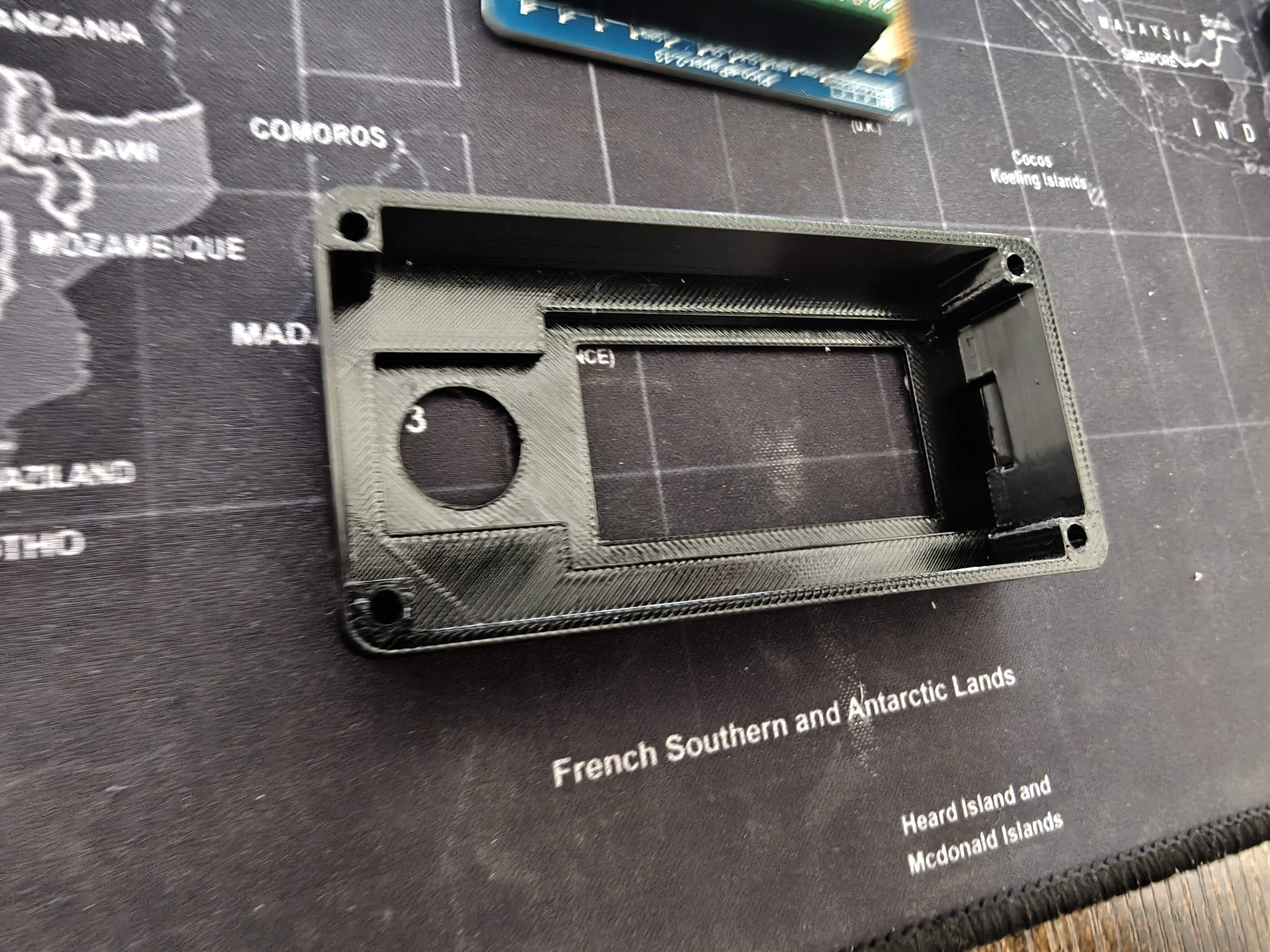
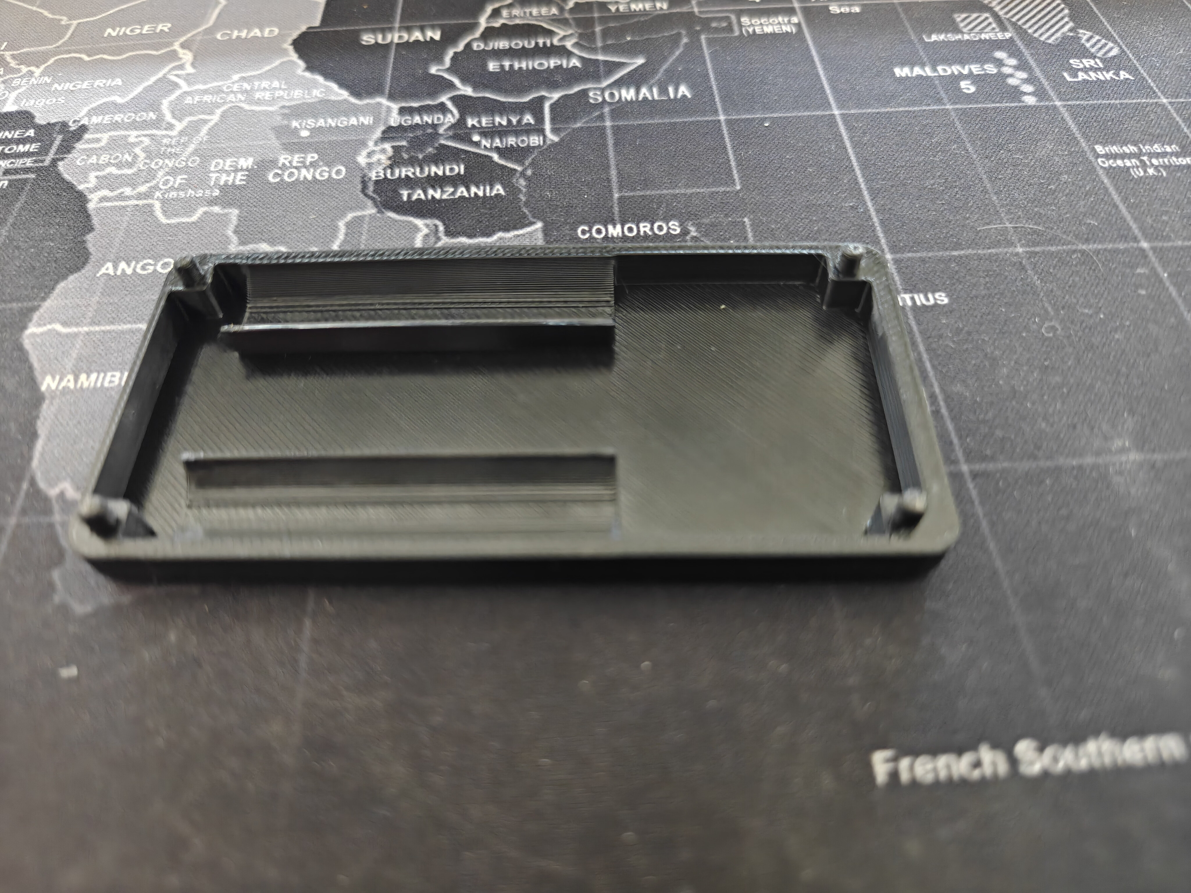
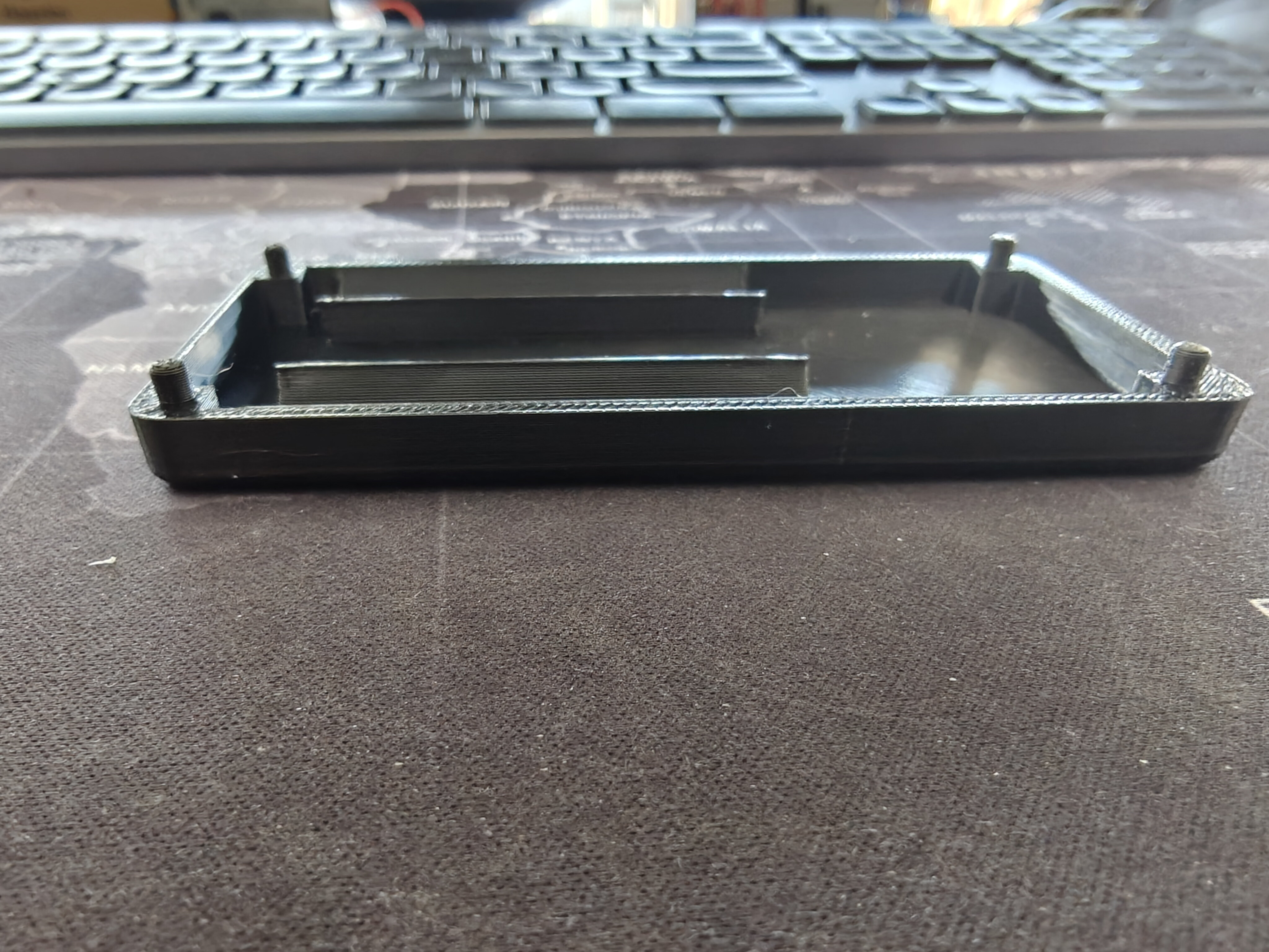
Base plate v3
The updated base plate with two support blocks for TP4056 retention, battery troughs along the long sides, four corner peg pillars, and the USB-C stadium notch.
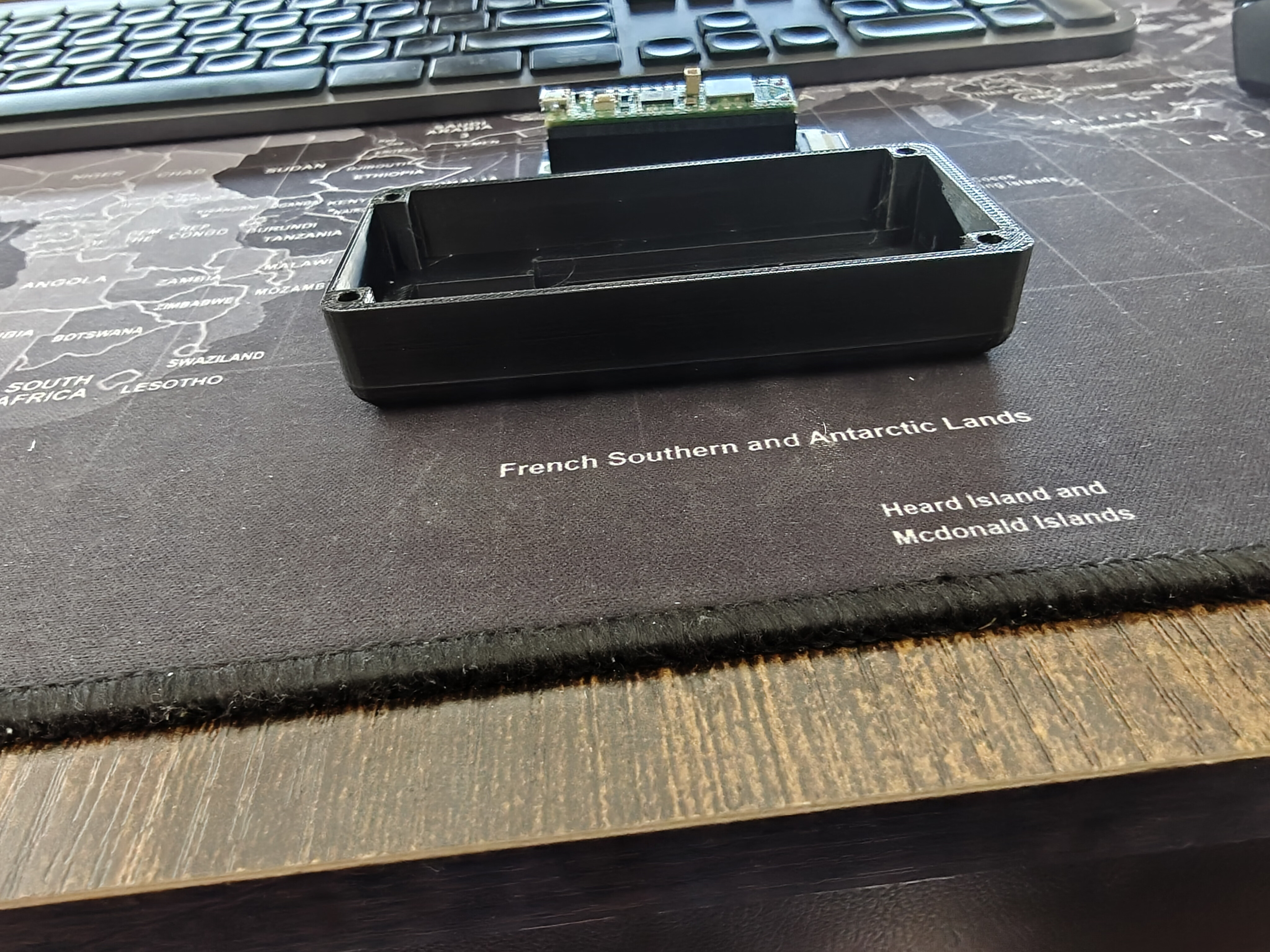
Assembled stack
The two-piece stack mated. The base plate's corner pegs slot into the top cover's blind M3 bores.
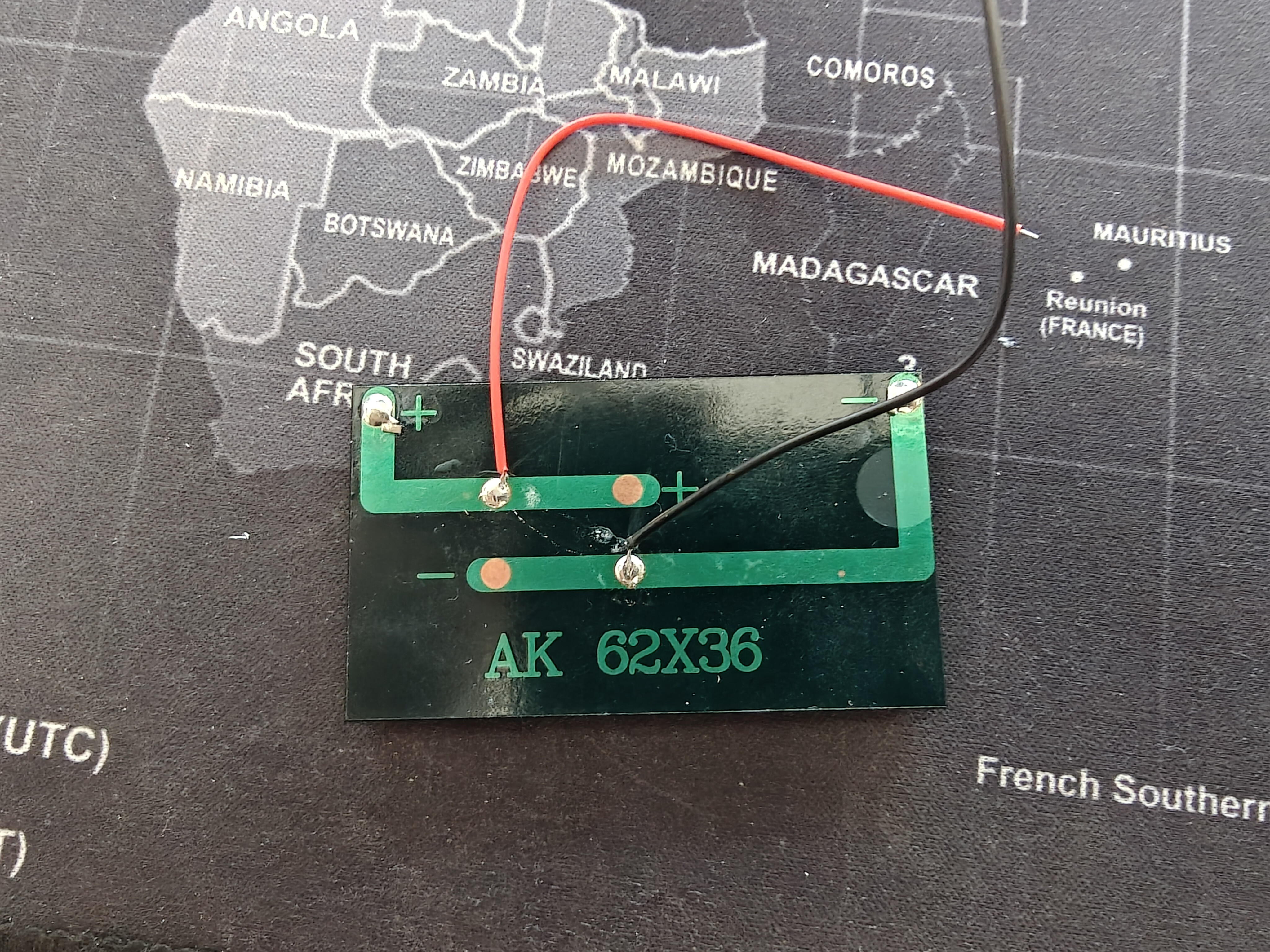
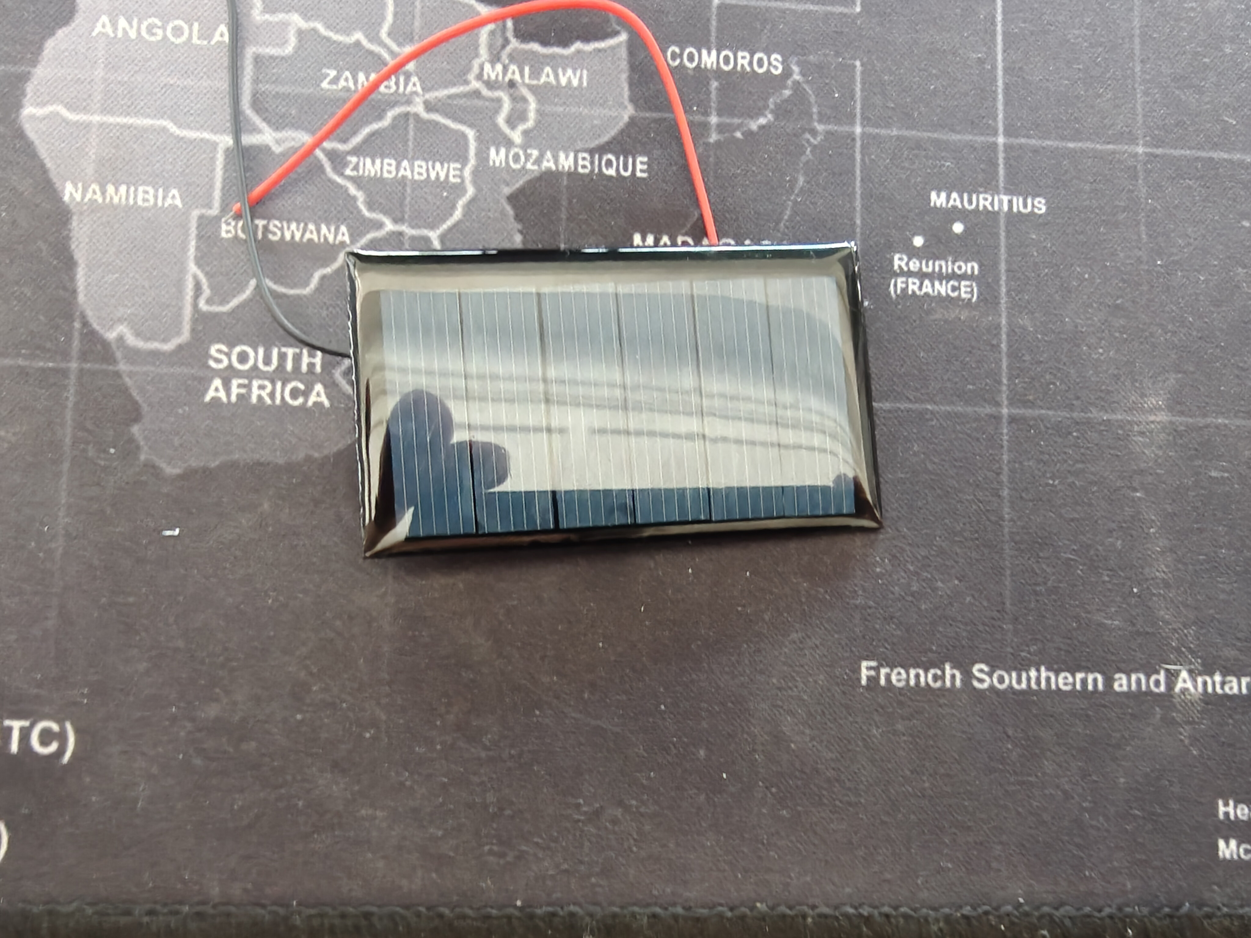
Solar panel — future charging
A small 62x36mm solar panel (AK 62X36) with pre-soldered red and black leads. This is being evaluated for trickle-charging the AAA batteries through the TP4056's input. The panel's 5V/100mA output is within the TP4056's input spec.
Next steps
- Wire batteries to the board — solder battery contacts to Pico VSYS and TP4056 B+/B-
- Design joystick breakout PCB — KiCad project already created (SKRHABE010 on 20x20mm board), ready for JLCPCB order
- Test solar charging — measure the AK 62x36 panel output and verify TP4056 charging behavior
Source: 04-25-design-alterations/