5-Way Navigation Joystick — Wiring & Setup Guide
Complete wiring, setup, and testing instructions for the DollaTek 5-Way Navigation Button Module connected to the Raspberry Pi Pico W.
Table of Contents
- Overview
- Component Details
- Prerequisites
- Pin Assignments
- Step-by-Step Wiring
- Wiring Diagram
- Breadboard Layout Strategy
- Software Setup
- Testing
- GPIO Budget After Wiring
- Future Expansion Compatibility
- Troubleshooting
Overview
The DollaTek 5-Way Navigation Button Module is a compact 5-direction rocker joystick with discrete digital outputs for Up, Down, Left, Right, and Center (press). Unlike an analog joystick, each direction is a simple switch that connects to ground when activated — making it ideal for menu navigation on the Dilder's e-ink display.
This module replaces the five individual 6x6mm tactile buttons originally planned for the project. The wiring is identical in principle (active-LOW with internal pull-ups) but the module provides a cleaner single-component solution.
Key characteristics:
| Property | Value |
|---|---|
| Input type | Digital (switch-to-ground per direction) |
| Directions | Up, Down, Left, Right, Center |
| Output | Active LOW (pressed = 0, released = 1) |
| Required resistors | None (uses Pico W internal pull-ups) |
| Operating voltage | 3.3V compatible |
| Module dimensions | ~25 × 25mm |
Component Details
| Attribute | Value |
|---|---|
| Product | DollaTek 5pcs Five Direction Navigation Button Module |
| Connector | 7-pin header (COM + 5 directions + optional VCC) |
| Interface | GPIO digital input |
| Amazon link | B07HBPW3DF |
| Pack quantity | 5 modules |
| Cost | ~€8.17 for 5 units (~€1.63 each) |
Prerequisites
Before wiring the joystick module, ensure you have:
- [x] Raspberry Pi Pico W (or Pico WH) on a breadboard
- [x] Waveshare 2.13" e-Paper display already wired and working (see Wiring & Pinout)
- [x] Male-to-male jumper wires (5 signal + 1 ground = 6 wires minimum)
- [x] USB cable connected to dev machine for serial output
- [x] Pico SDK or MicroPython environment set up (see Dev Environment)
Pin Assignments
These GPIO pins were chosen to:
- Sit adjacent on the Pico W's left edge (physical pins 4–9) for clean wiring
- Avoid SPI1 (used by the e-ink display on GP8–GP13)
- Leave SPI0, I2C0, I2C1, and UART0 free for future peripherals
| Direction | Module Pin | Pico W GPIO | Physical Pin | Pull-up |
|---|---|---|---|---|
| Up | UP | GP2 | Pin 4 | Internal (software) |
| Down | DOWN | GP3 | Pin 5 | Internal (software) |
| Left | LEFT | GP4 | Pin 6 | Internal (software) |
| Right | RIGHT | GP5 | Pin 7 | Internal (software) |
| Center | SET / MID | GP6 | Pin 9 | Internal (software) |
| Ground | COM / GND | GND | Pin 8 | — |
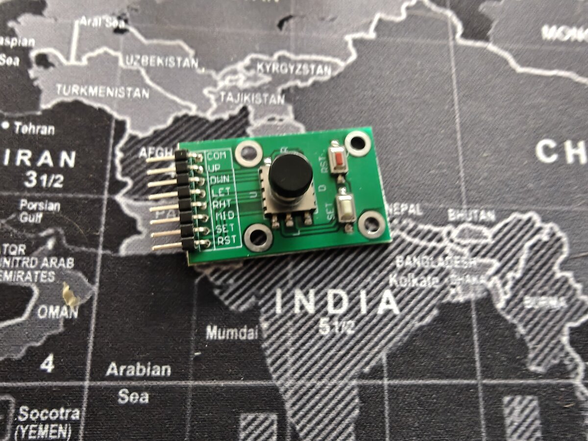
Pin labeling varies
Different batches of this module may label the center button as SET, MID, CENTER, or SW. The ground pin may be labeled COM or GND. Check your specific module's silkscreen.
Step-by-Step Wiring
Step 1 — Identify the Module Pins
Examine the module's PCB silkscreen. You should see 5 direction labels and a common ground pin. The pin order (left to right) varies by batch — always read the silkscreen, do not assume the order matches this guide.
Common pin layouts:
Layout A:  COM  UP  DOWN  LEFT  RIGHT  SET
Layout B:  GND  UP  DWN   LFT   RGT    MID
Layout C:  COM  UP  DOWN  LEFT  RIGHT  CENTER  VCC
If your module has a VCC pin, leave it unconnected — we do not need external power for the switches.
Step 2 — Power Off the Pico W
Disconnect USB first
Always unplug the Pico W's USB cable before connecting or disconnecting any wires. This prevents accidental shorts and protects the GPIO pins.
Step 3 — Connect Ground
Using a male-to-male jumper wire:
- Connect the module's COM / GND pin to the Pico W's GND at physical pin 8
- Alternatively, connect to any GND pin on the breadboard's ground rail if you have the rail bridged to a Pico GND pin
This is the common return path for all five switches.
Step 4 — Wire the Direction Pins
Connect each direction pin on the module to its assigned GPIO on the Pico W:
| Wire # | From (module) | To (Pico W) | Physical pin |
|---|---|---|---|
| 1 | UP | GP2 | Pin 4 |
| 2 | DOWN | GP3 | Pin 5 |
| 3 | LEFT | GP4 | Pin 6 |
| 4 | RIGHT | GP5 | Pin 7 |
| 5 | CENTER / SET | GP6 | Pin 9 |
Color coding
Use consistent wire colors for easy debugging later. Suggested: Red=UP, Blue=DOWN, Yellow=LEFT, Green=RIGHT, White=CENTER, Black=GND.
Step 5 — Verify Wiring
Before powering on, visually confirm:
- No shorts — no two signal wires touch each other or the ground wire
- Correct pins — double-check each wire goes to the right GPIO (GP2–GP6, not GP8–GP13 which are the display)
- Ground connection — COM/GND wire goes to a Pico W GND pin, not a GPIO pin
- No VCC — if the module has a VCC pin, it should be unconnected
Wiring Diagram
DollaTek 5-Way Module              Pico W (on breadboard)
┌──────────────────┐               ┌───USB───┐
│                  │        GP0  [ 1]         [40]  VBUS
│  COM ────────────┼────── GP1  [ 2]         [39]  VSYS
│                  │        GND  [ 3]         [38]  GND
│  UP  ────────────┼─────▶ GP2  [ 4]         [37]  3V3_EN
│                  │               ├──────────┤
│  DOWN ───────────┼─────▶ GP3  [ 5]         [36]  3V3(OUT) ── e-ink VCC
│                  │               ├──────────┤
│  LEFT ───────────┼─────▶ GP4  [ 6]         [35]  ADC_VREF
│                  │               ├──────────┤
│  RIGHT ──────────┼─────▶ GP5  [ 7]         [34]  GP28
│                  │               ├──────────┤
│  COM ────────────┼─────▶ GND  [ 8]         [33]  AGND
│                  │               ├──────────┤
│  CENTER ─────────┼─────▶ GP6  [ 9]         [32]  GP27
│                  │               ├──────────┤
│  (VCC — NC)      │        GP7  [10]         [31]  GP26
│                  │               ├──────────┤
└──────────────────┘        GP8  [11] ◄── DC  [30]  RUN
                            GP9  [12] ◄── CS  [29]  GP22
                            GND  [13]         [28]  GND
                           GP10  [14] ◄── CLK [27]  GP21
                           GP11  [15] ◄── DIN [26]  GP20
                           GP12  [16] ◄── RST [25]  GP19
                           GP13  [17] ◄── BUSY[24]  GP18
                            GND  [18]         [23]  GND
                           GP14  [19]         [22]  GP17
                           GP15  [20]         [21]  GP16
                                 └─────────┘

▶ = Joystick module connections (pins 4–9, left side)
◄ = e-Paper display connections (pins 11–17, left side)
Breadboard Layout Strategy
The Pico W's left edge is divided into two clean zones:
| Zone | Physical Pins | Function | Wires |
|---|---|---|---|
| Top-left | 4–9 (GP2–GP6 + GND) | Joystick module | 6 wires |
| Mid-left | 11–17 (GP8–GP13) | e-Paper display SPI | 6 wires |
This separation keeps the joystick and display wiring physically apart, reducing clutter and making debugging easier.
Recommended breadboard placement:
- Pico W sits centered on the breadboard, straddling the center channel
- Joystick module sits to the left of the breadboard, wired to the top-left Pico pins
- e-Paper display connects from the right side or via flying wires to mid-left pins
- Ground rail on the breadboard bridges all GND connections
Software Setup
C (Pico SDK)
Add button GPIO initialization to your firmware. This can be added after DEV_Module_Init():
#include "pico/stdlib.h"

// Joystick GPIO assignments
#define BTN_UP      2
#define BTN_DOWN    3
#define BTN_LEFT    4
#define BTN_RIGHT   5
#define BTN_CENTER  6

void joystick_init(void) {
    const uint buttons[] = {BTN_UP, BTN_DOWN, BTN_LEFT, BTN_RIGHT, BTN_CENTER};
    for (int i = 0; i < 5; i++) {
        gpio_init(buttons[i]);
        gpio_set_dir(buttons[i], GPIO_IN);
        gpio_pull_up(buttons[i]);
    }
}

// Returns true if button is currently pressed (active LOW)
bool joystick_pressed(uint gpio) {
    return gpio_get(gpio) == 0;
}
MicroPython
from machine import Pin

BUTTONS = {
    'up':     Pin(2, Pin.IN, Pin.PULL_UP),
    'down':   Pin(3, Pin.IN, Pin.PULL_UP),
    'left':   Pin(4, Pin.IN, Pin.PULL_UP),
    'right':  Pin(5, Pin.IN, Pin.PULL_UP),
    'center': Pin(6, Pin.IN, Pin.PULL_UP),
}

def is_pressed(name):
    """Returns True if the named button is currently pressed."""
    return BUTTONS[name].value() == 0
Testing
Quick Polling Test (C)
Flash this to the Pico W to verify all five directions register correctly:
#include <stdio.h>
#include "pico/stdlib.h"

#define BTN_UP      2
#define BTN_DOWN    3
#define BTN_LEFT    4
#define BTN_RIGHT   5
#define BTN_CENTER  6

int main() {
    stdio_init_all();
    sleep_ms(2000);  // Wait for USB serial to connect

    const uint buttons[] = {BTN_UP, BTN_DOWN, BTN_LEFT, BTN_RIGHT, BTN_CENTER};
    const char *names[]  = {"UP", "DOWN", "LEFT", "RIGHT", "CENTER"};

    for (int i = 0; i < 5; i++) {
        gpio_init(buttons[i]);
        gpio_set_dir(buttons[i], GPIO_IN);
        gpio_pull_up(buttons[i]);
    }

    printf("=== Joystick Test ===\n");
    printf("Press any direction...\n\n");

    while (1) {
        for (int i = 0; i < 5; i++) {
            if (gpio_get(buttons[i]) == 0) {
                printf("[PRESSED] %s (GP%d)\n", names[i], buttons[i]);
            }
        }
        sleep_ms(100);
    }
}
Serial Monitor Verification
- Flash the test firmware to the Pico W via UF2 or
picotool - Connect a serial terminal at 115200 baud:
# Using screen
screen /dev/ttyACM0 115200

# Using picocom
picocom -b 115200 /dev/ttyACM0

# Using minicom
minicom -b 115200 -D /dev/ttyACM0
- Press each direction on the joystick module
- You should see output like:
=== Joystick Test ===
Press any direction...

[PRESSED] UP (GP2)
[PRESSED] DOWN (GP3)
[PRESSED] LEFT (GP4)
[PRESSED] RIGHT (GP5)
[PRESSED] CENTER (GP6)
- Verify all five directions print correctly. If a direction never triggers, check the wiring for that specific pin.
Debounce Considerations
Mechanical switches bounce — a single press can produce multiple transitions within 1–5ms. For the test above, the 100ms polling interval naturally filters this out. For production firmware:
- Polling approach: Read at 50–100ms intervals (sufficient for menu navigation)
- Software debounce: Require the pin to stay LOW for 20ms before registering a press
- Hardware debounce: Not needed for this module at typical interaction speeds
The existing mood-selector firmware already handles input at an appropriate polling rate.
GPIO Budget After Wiring
With the joystick module wired, the updated pin budget is:
| Peripheral | GPIOs | Interface |
|---|---|---|
| e-Paper display | GP8–GP13 (6 pins) | SPI1 |
| 5-way joystick | GP2–GP6 (5 pins) | GPIO |
| Piezo buzzer (Phase 7) | GP15 (1 pin) | PWM |
| Total allocated | 12 pins | |
| Free | 14+ GPIO remaining |
Free pins available: GP0, GP1, GP7, GP14, GP16–GP22, GP26–GP28.
Future Expansion Compatibility
The joystick wiring was designed to leave key interfaces free for planned peripherals:
| Future Peripheral | Interface | GPIO Pins | Status |
|---|---|---|---|
| GPS module (e.g., NEO-6M) | UART0 | GP0 (TX), GP1 (RX) | Available |
| Accelerometer (LIS2DH12TR) | I2C0 | GP16 (SDA), GP17 (SCL) | Available |
| External flash / MicroSD | SPI0 | GP16–GP19 | Available |
| Piezo buzzer | PWM | GP15 | Reserved (Phase 7) |
| Battery monitoring | ADC | GP29 (ADC3) | Available |
All four interfaces (SPI0, I2C0, UART0, PWM) remain completely unoccupied, allowing the joystick, display, GPS, and accelerometer to all coexist with zero conflicts.
Troubleshooting
| Symptom | Likely Cause | Fix |
|---|---|---|
| No direction registers | COM/GND not connected | Check ground wire from module COM to Pico GND |
| One direction doesn't work | Wrong GPIO or loose wire | Verify the specific wire with a multimeter for continuity |
| All directions read as pressed | Signal wires shorted to GND | Check for solder bridges or bent pins on the module |
| All directions read as released | Pull-ups not enabled | Ensure gpio_pull_up() is called for each pin in software |
| Multiple directions trigger at once | Wires swapped or shorted | Re-check each wire against the pin table above |
| Rapid repeated triggers | Switch bounce | Add 20ms debounce delay in software (see Debounce Considerations) |
[PRESSED] prints but display doesn't respond |
Test code is polling-only | The test firmware only prints to serial — display integration is in the mood-selector firmware |
| Serial terminal shows nothing | Wrong baud rate or no CDC | Use 115200 baud; ensure firmware calls stdio_init_all() |
Related Pages
- Wiring & Pinout — Full GPIO pin map and display wiring
- Materials List — All components needed for the build
- Pico W Reference — Full Pico W technical specifications
- Keyboard-to-Pico Input — Serial input mapping for development