ESP32-S3 Enclosure (SCAD)
A parametric 5-piece case for the Olimex ESP32-S3-DevKit-Lipo + Waveshare 2.13" e-paper + 1000mAh battery. Everything in one OpenSCAD file, exported as 3MF for Bambu Studio.
Source: hardware-design/esp32s3-enclosure.scad · Prints: hardware-design/enclosure-prints/
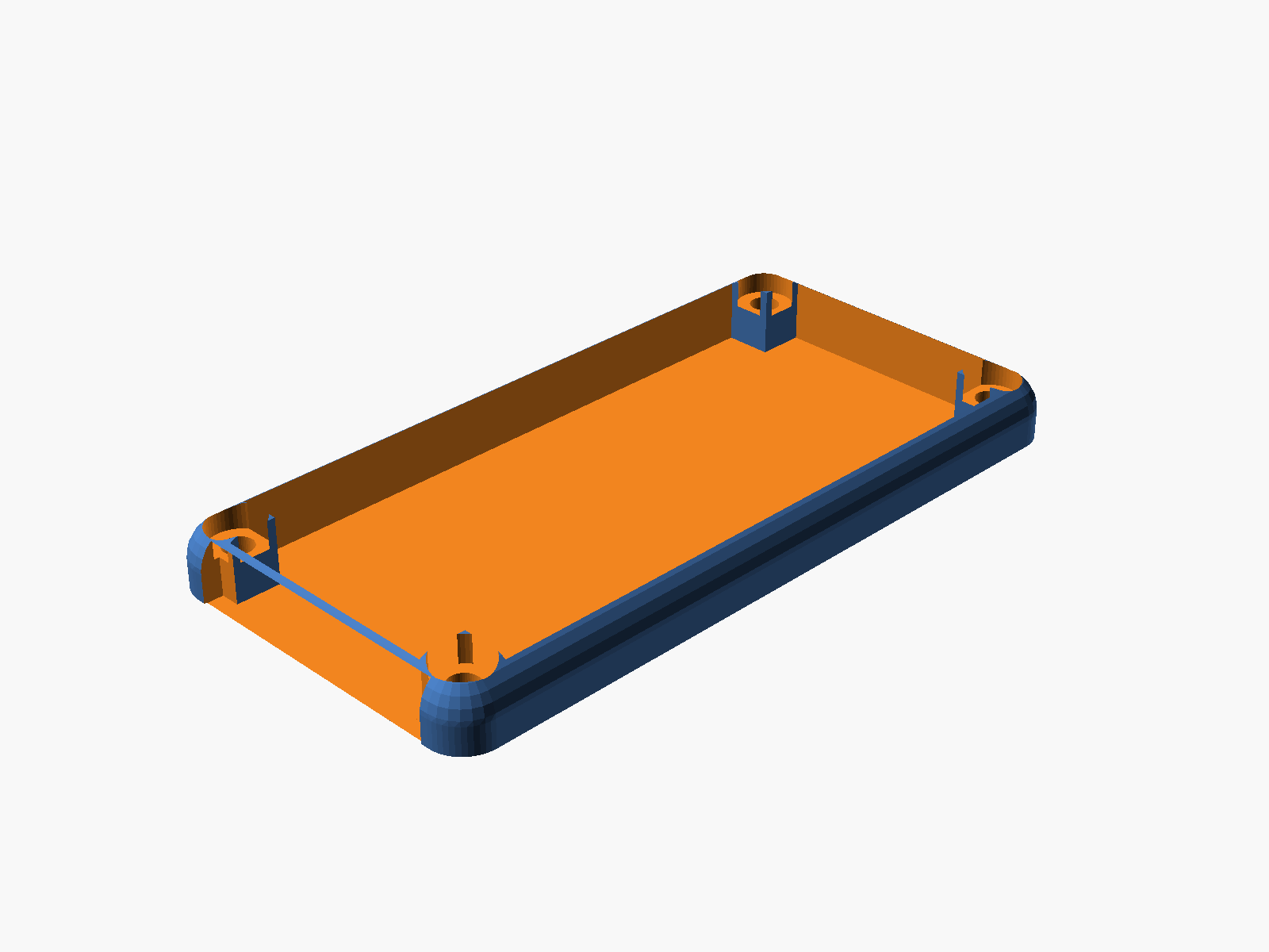
Preview
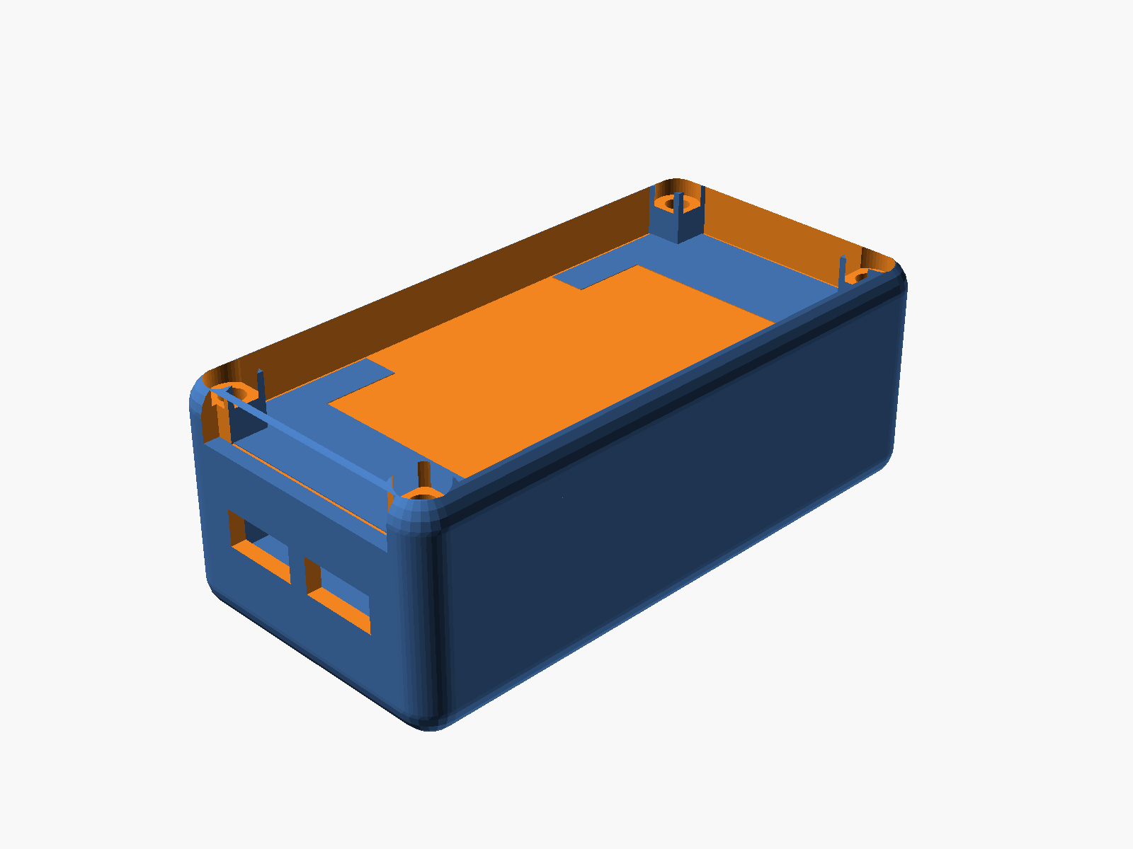
The stack from bottom to top:
| Layer | Z range (mm) | Purpose |
|---|---|---|
| Base floor | 0 – 2 | Battery tray, curved bottom |
| Battery chamber | 2 – 8 | 1000mAh LiPo (35 × 52 × 5mm) sits here |
| Middle plate | 8 – 10 | Board tray; rests on shelf; header-pin slots |
| Board + WROOM | 10 – 14.8 | ESP32-S3 PCB (56 × 28mm) + module |
| Display | 15.8 – 20.8 | Waveshare 2.13" (30 × 65 × 5mm), snap-held |
| Top-mid plate | 20.8 – 22.8 | Flush with base top edge, has viewing window + wire hole |
| Cover | 22.8 – 29.8 | Open-top shell with corner posts + rounded walls |
Outer footprint 39.8 × 79.8 × 29.8 mm.
The five printable pieces
Base
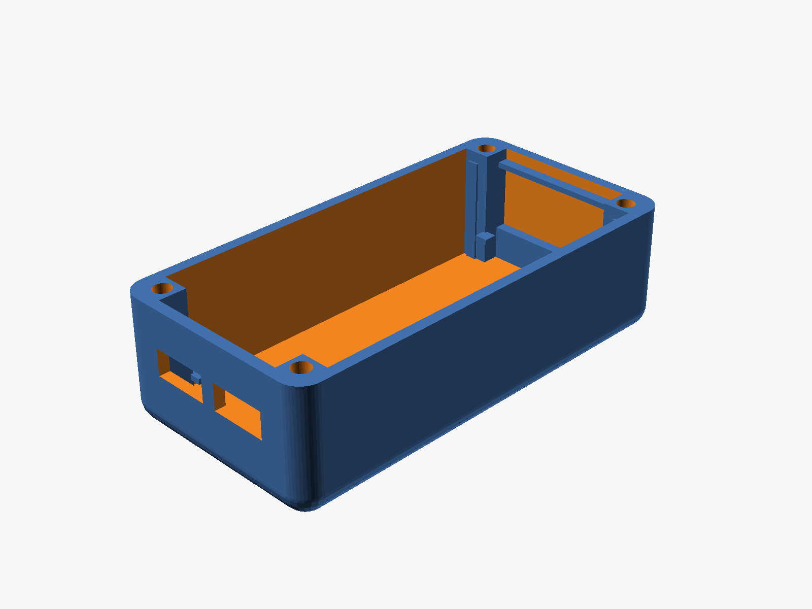
- Rounded outer shell with 4mm vertical-edge radius
- Curved bottom via sphere-offset trick (~30° overhang, FDM-printable upright)
- 4 corner pillars (5×5mm) with M3 screw channels floor-to-top
- 2 USB-C cutouts on the -Y short wall (9.5 × 4mm, centered on board's USB-C Z)
- Lower shelf at z=8 — 2mm inward ledges on the short walls + 4 pillar-corner tabs (all extended down to the floor as a rib, printable without overhangs)
- Upper shelf at z=20.8 — thin ledges only (tabs skipped; would have hit the display)
- 4 internal corner posts at the display corners for lateral display constraint
Middle plate (board tray)
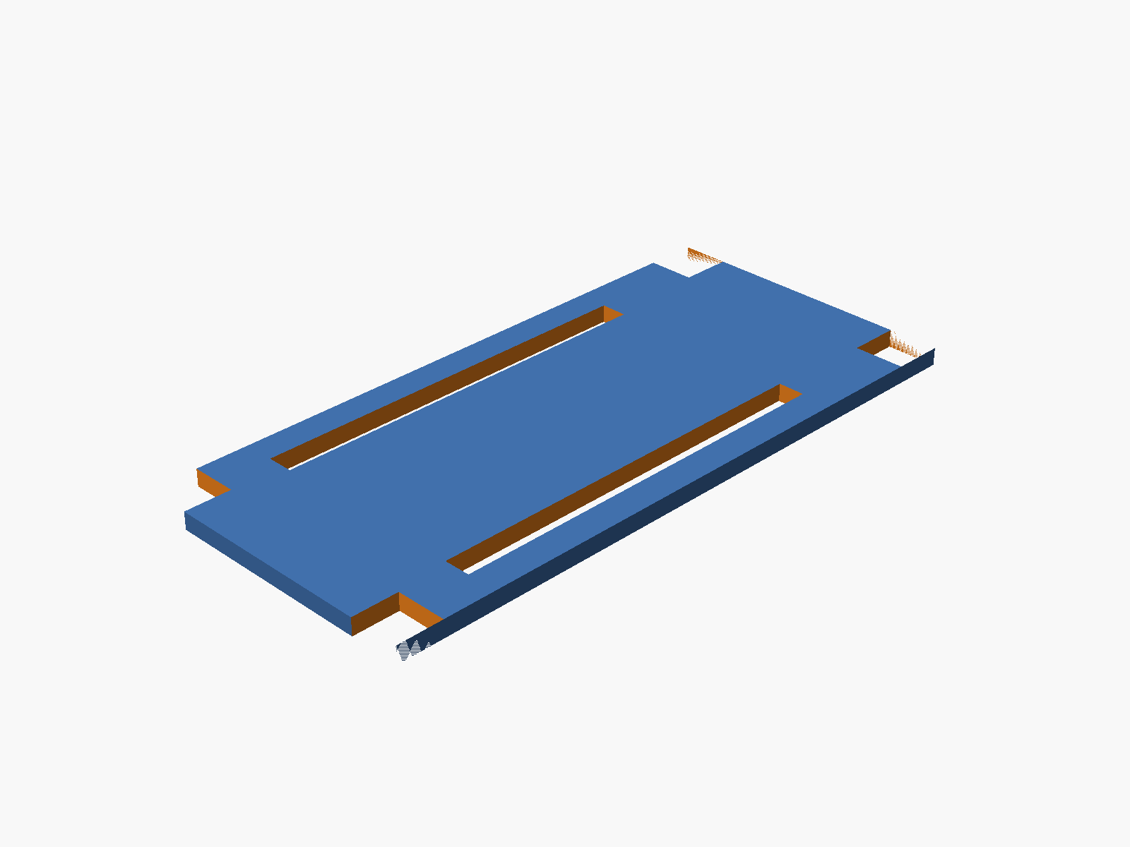
Drops in and rests on the lower shelf. 35 × 75 × 2mm with:
- 4 corner notches for the base pillars
- 2 header-pin slots along the long edges (3mm × 46mm)
- 4 M3 clearance holes at pillar centers
Top-mid plate
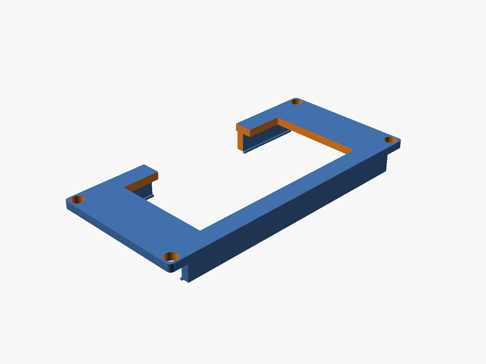
Drops into the cavity and rests on the upper shelf, flush with the base top.
- Display viewing window — 25 × 50mm centered, opens the view from the cover down to the display
- Wire pass-through — 30 × 6mm hole on the -X long edge, cut through plate + snap rail + bottom lip, for fishing wires out to an external sensor or connector
- Two long snap rails on the underside — 2 × 5 × 65mm walls at each long edge with a 0.5mm inward lip at the bottom. When pressed down over a pre-placed display, the rails flex outward, the lips pass the display edges, then snap back with the lips engaging under the display's bottom face
Cover
Open-top shell with same footprint as the base for fully flush outer edges.
- No top plate (view window is the entire open top)
- 4 corner posts preserved inside for screw material
- M3 clearance holes + counterbores for socket heads at each corner
- Rounded vertical edges (matches base)
- Rounded top corners (sphere hull) for the curvy top look
- 30 × 6mm wire notch at the bottom of the -Y short wall for external pass-through
Screws (plastic plugs)
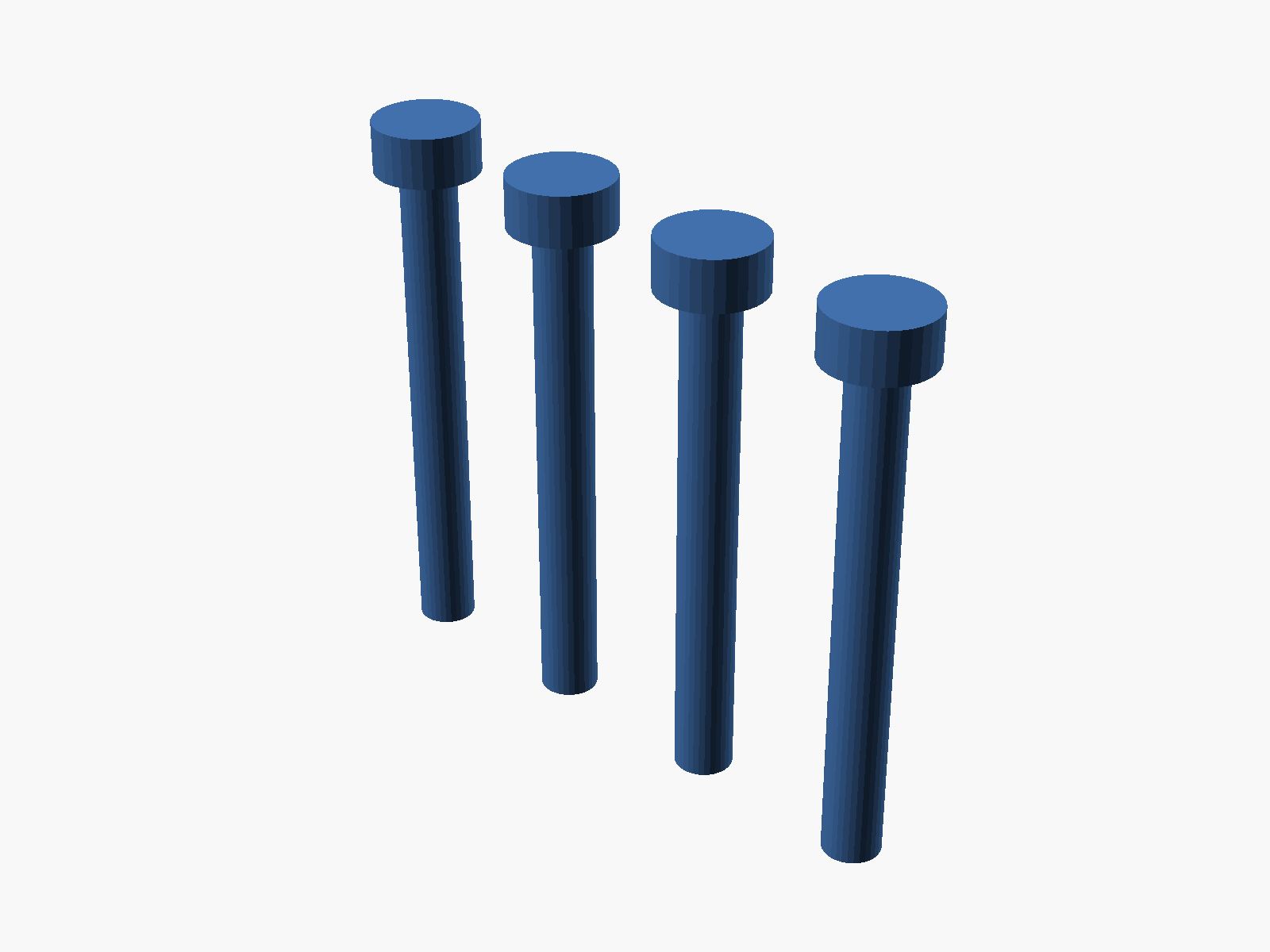
Plastic-weldable plugs — 4 arranged in a row for efficient printing.
- Ø 3.0mm shank (fits the 3.2mm clearance holes)
- Ø 5.6 × 2.7mm head (seats in the 6mm counterbore)
- Total length 26.8mm — spans the full stack
- Print in the same material as the case. After assembly, heat the head with a soldering iron to fuse it into the cover — permanent one-way seal
Assembly order
- Battery drops into the base floor cavity
- Middle plate drops in, rests on the lower shelf at z=8; board sits on it
- Display drops in between the 4 corner posts at z=15.8–20.8
- Top-mid plate presses down over the display — the long rails flex outward, the bottom lips pass the display edges, then snap back with the lips under the display. Plate top is flush with the base top
- Cover drops over the stack (edges aligned with the base)
- 4 screw plugs insert through the counterbores, shank reaches the base floor
- (Optional) heat each plug head to weld the case shut permanently
Parameters (top of SCAD file)
All dimensions are parametric. Common tweaks:
// Rounding
case_corner_r  = 4;      // vertical edge radius on base + cover
plate_corner_r = 1;      // vertical edge radius on plates
base_bot_cut   = 0;      // 0 = bottom tapers to points (print flipped); 2 = upright-printable

// Display snap rails (underside of top-mid plate)
snap_rail_w    = 2;      // rail thickness
snap_lip_d     = 0.5;    // how far the bottom lip protrudes inward
snap_lip_h     = 0.5;    // lip thickness

// Viewing + wiring
topmid_window_w   = 25;  // display viewing window (width)
topmid_window_l   = 50;  // display viewing window (length)
wire_hole_len     = 30;  // wire pass-through (along Y)
wire_hole_depth   = 6;   // wire pass-through (depth from edge)

// Clearance
slop           = 0.4;    // tolerance around plates and the cover/base fit
Exporting for your slicer
Each piece renders separately via the part variable. From the repo root:
mkdir -p hardware-design/enclosure-prints
cd hardware-design/enclosure-prints
for p in base middle topmid cover screws; do
  openscad -D "part=\"$p\"" -o $p.3mf ../esp32s3-enclosure.scad
done
All five exports come out as CGAL-simple (manifold) volumes — import straight into Bambu Studio or any FDM slicer.
Print orientation notes
- Base — with
base_bot_cut = 0, the bottom tapers to points at z=0. Print flipped: the flat top (where the cover sits) goes on the build plate, the curvy bottom points up. If you'd rather print upright, setbase_bot_cut = 2for a gentler ~30° taper (still matches the cover's curve reasonably). - Cover — prints upright as-is. Flat bottom on the bed, rounded top grows inward (no overhangs).
- Middle, top-mid — flat plates, print flat on the bed. The snap rails on the top-mid plate hang below the plate; print that one upside-down (rails pointing up) to avoid any supports.
- Screws — small plugs, print flat (head up) with a brim if you have any bed-adhesion issues on small parts.
Why the stack looks the way it does
A few design decisions that took a few iterations to land on:
- Flush top-mid plate — the base walls rise to
z_disp_top + plate_thk(22.8mm), so the plate's top surface is level with the base top edge. No lip sticking up, no gap around the plate. - Base display rails stop at the top-mid plate bottom — the 4 corner posts end at z=20.8 instead of going through the top-mid plate. This leaves the plate solid on top (no through-holes / visible gaps).
- Shelves extend to the floor — the lower shelf is a full rib from z=2 to z=8 rather than a thin floating ledge. Cleaner FDM prints.
- Cover wraps on the sides instead of overlapping — cover outer matches base outer; the two meet edge-to-edge for a continuous curve down the side. Fastening happens through the 4 corner screws/plugs, not via a wrap-over fit.
- Snap rails on the plate, not the base — the rails belong to the top-mid plate so they descend onto the display during final assembly. The display goes in first, then the plate is pressed down and the lips snap under the display edges.
Open questions / future tweaks
- USB-C cutout positions are centered pair with 13mm spacing — verify against your actual Olimex board and nudge if needed.
- Display window is sized for the visible e-paper area (25 × 50mm); if your Waveshare revision has a slightly different active area, adjust
topmid_window_w / topmid_window_l. - With the antenna now fully inside the case, Wi-Fi range may be slightly reduced. If you need to expose the antenna, cut a slot on the +Y short wall at the antenna's Z range (board top + 3.2mm); the SCAD has
antenna_wid/antenna_projparameters already defined.