AAA Cradle Insert + Base Plate — Splitting the Stack into Three Parts
Up to this point the Rev 2 stack has been either three pieces (base + middle-platform + top-cover) or two pieces (base-v3-2piece + top-cover). This session adds a fourth design path: a drop-in AAA cradle that lives in the cover's negative space, plus a shallow base plate that snaps into the cover via four corner pegs. The middle platform goes away entirely; what was carried by the base now gets carried by the cradle insert and the base plate together.
First prints — 2026-04-25
The cradle insert and base plate printed on the Bambu A1 Mini. Here's how they came out:
Cradle insert standalone
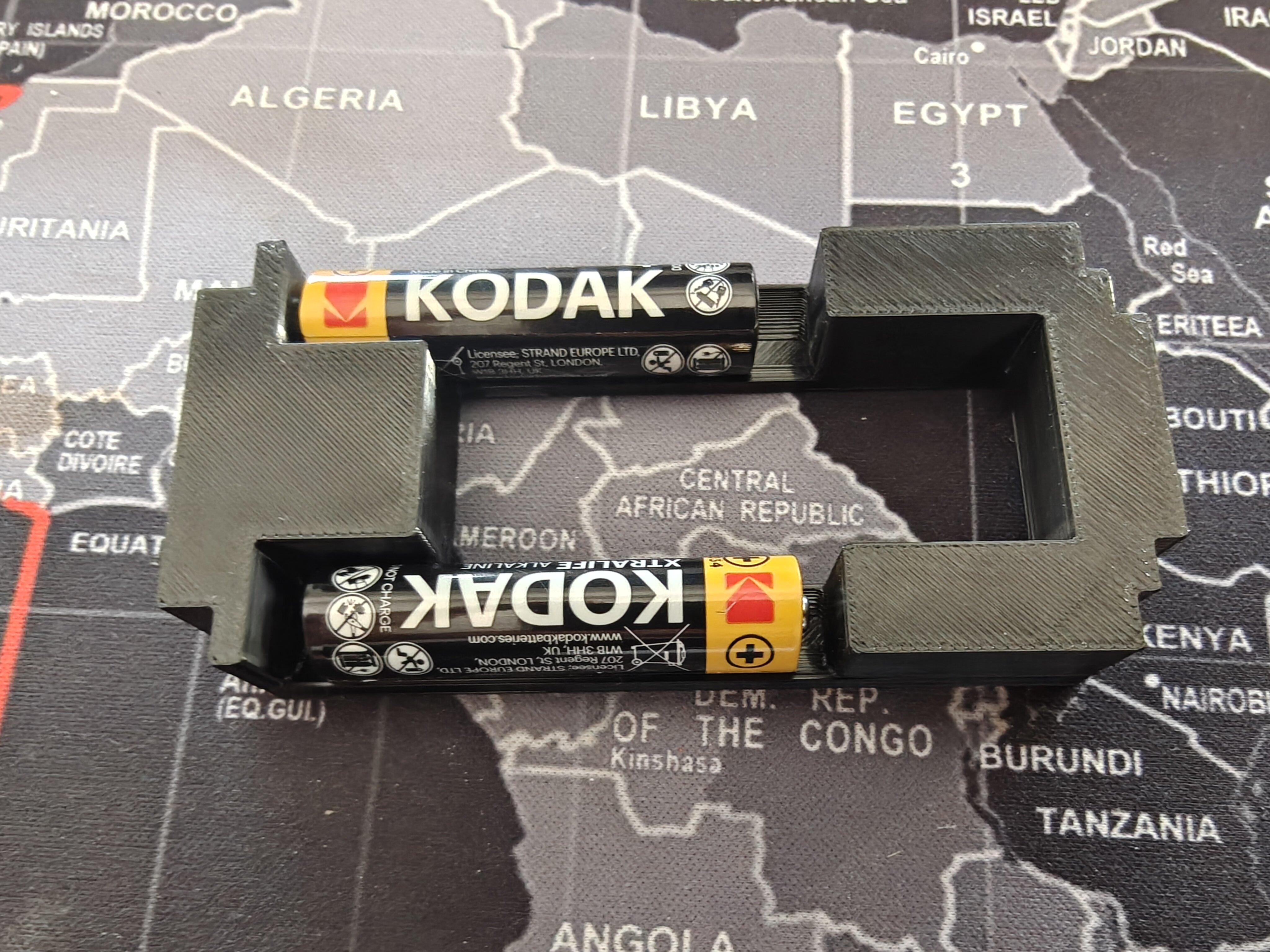
The cradle insert by itself, with two AAA cells (Kodak Xtralife stand-ins for the 10440 Li-ion cells on order) loaded in the ±Y bays. The center Pico nest cutout and the connecting block at the -X end are clearly visible.
Assembled stack — cradle + base plate + Pico 2 W
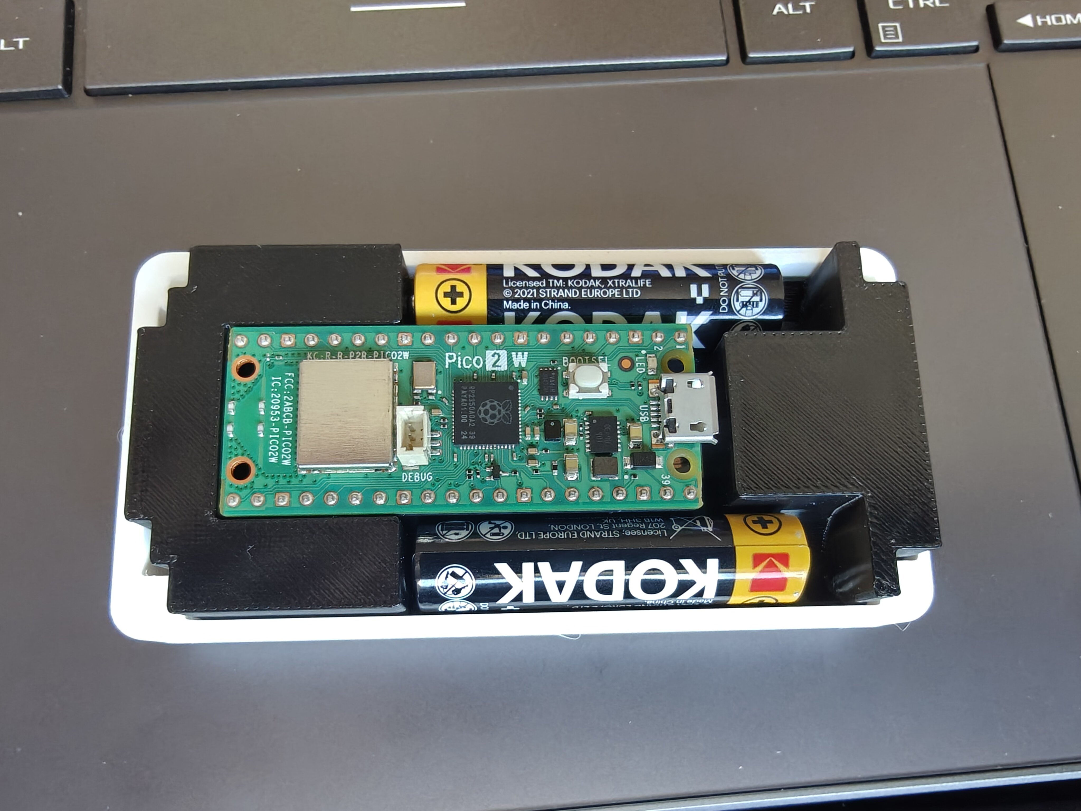
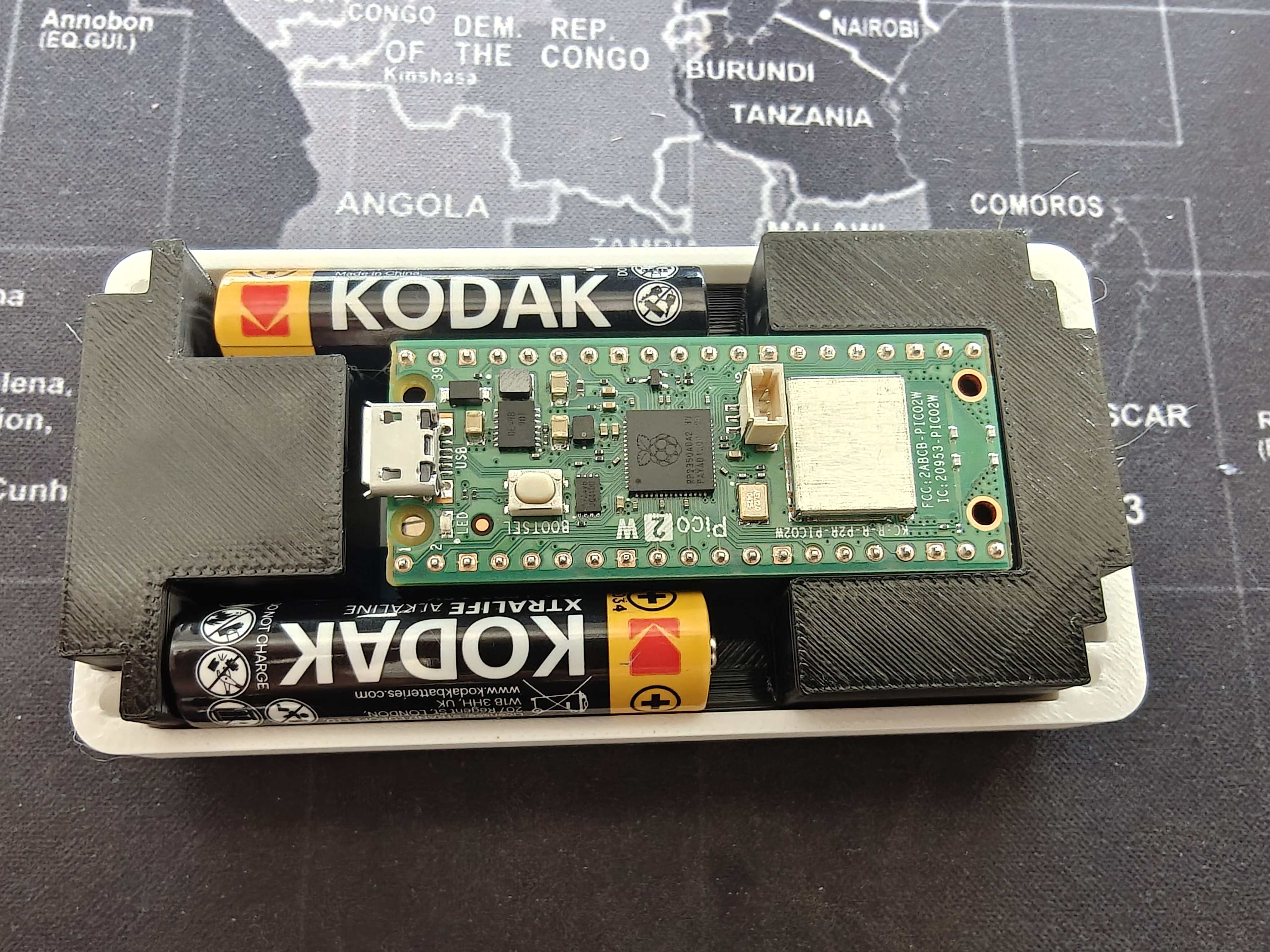
The cradle drops into the base plate's pocket, then the Pico 2 W nests into the center cutout between the two cells. The base plate's four corner pegs engage the cover's blind M3 bores above.
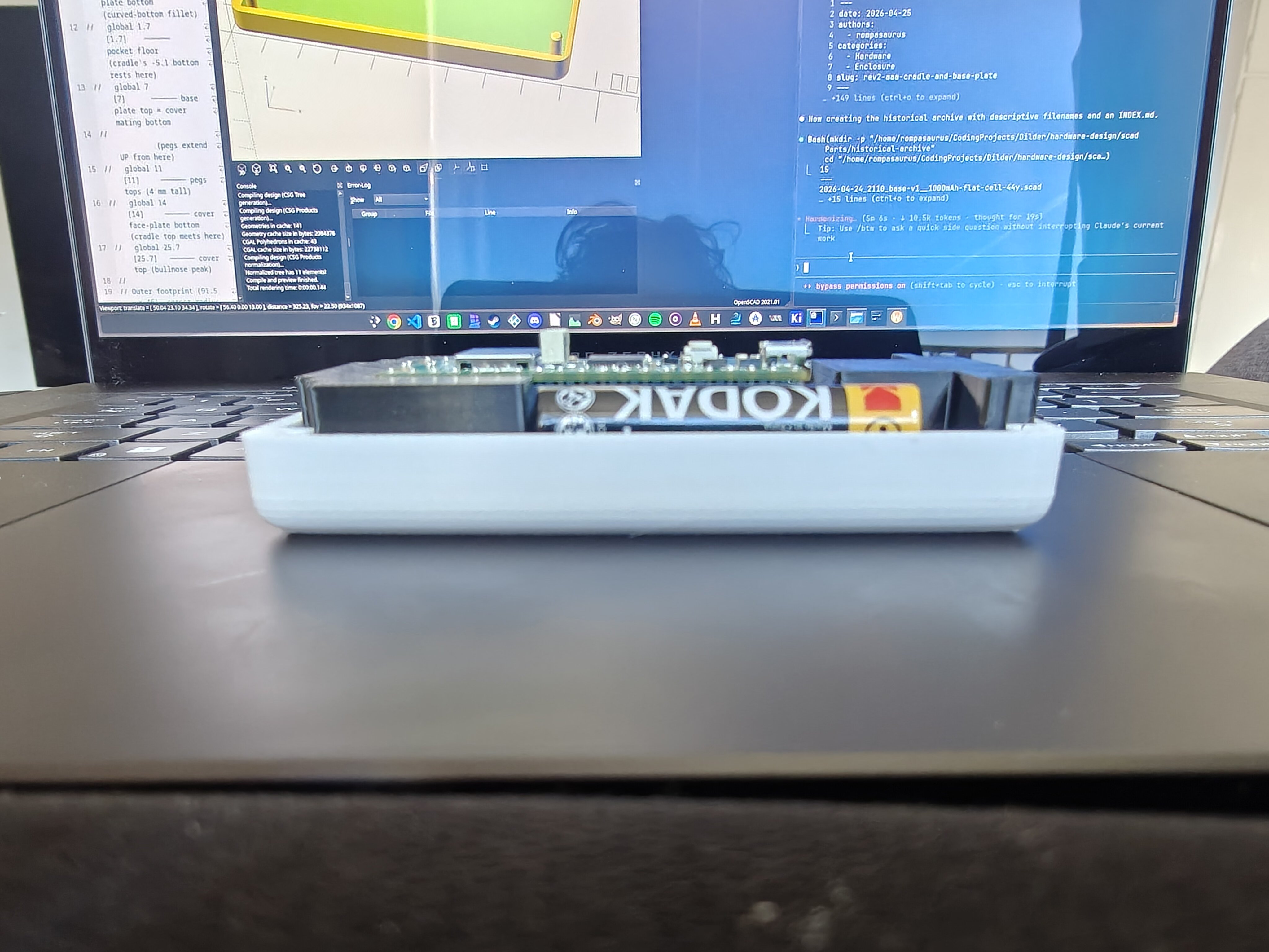
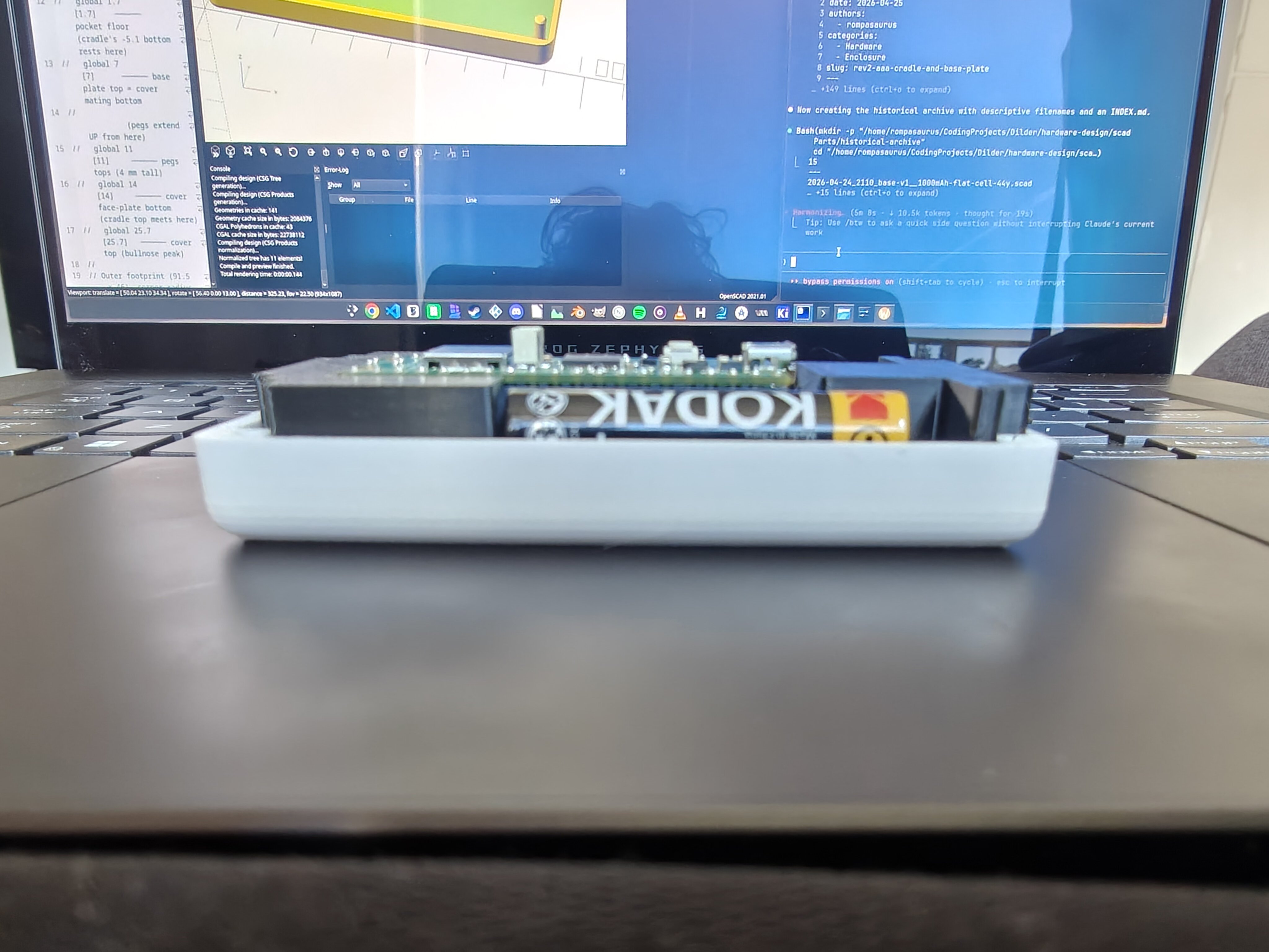
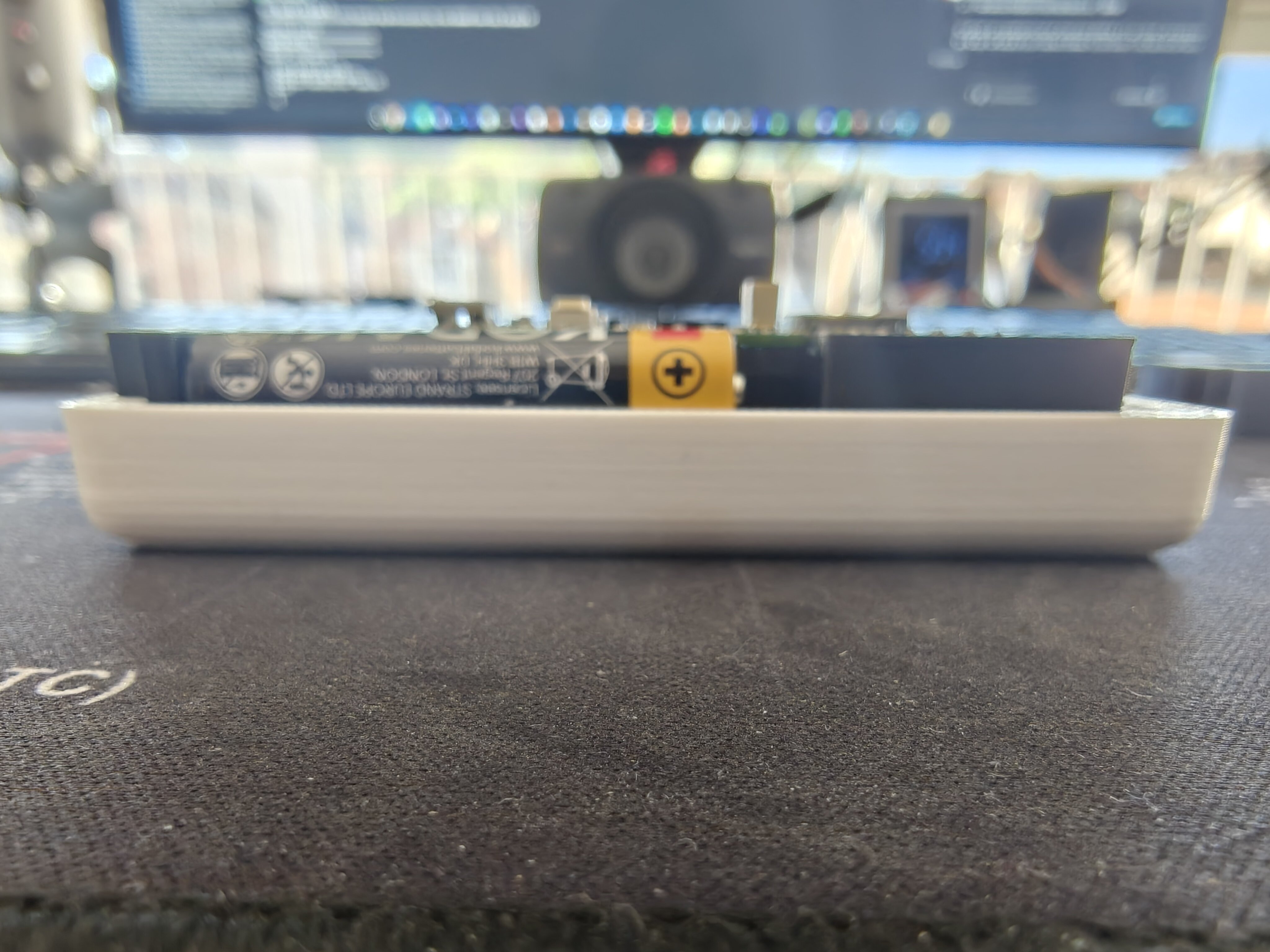
Side profile — how thin is it?
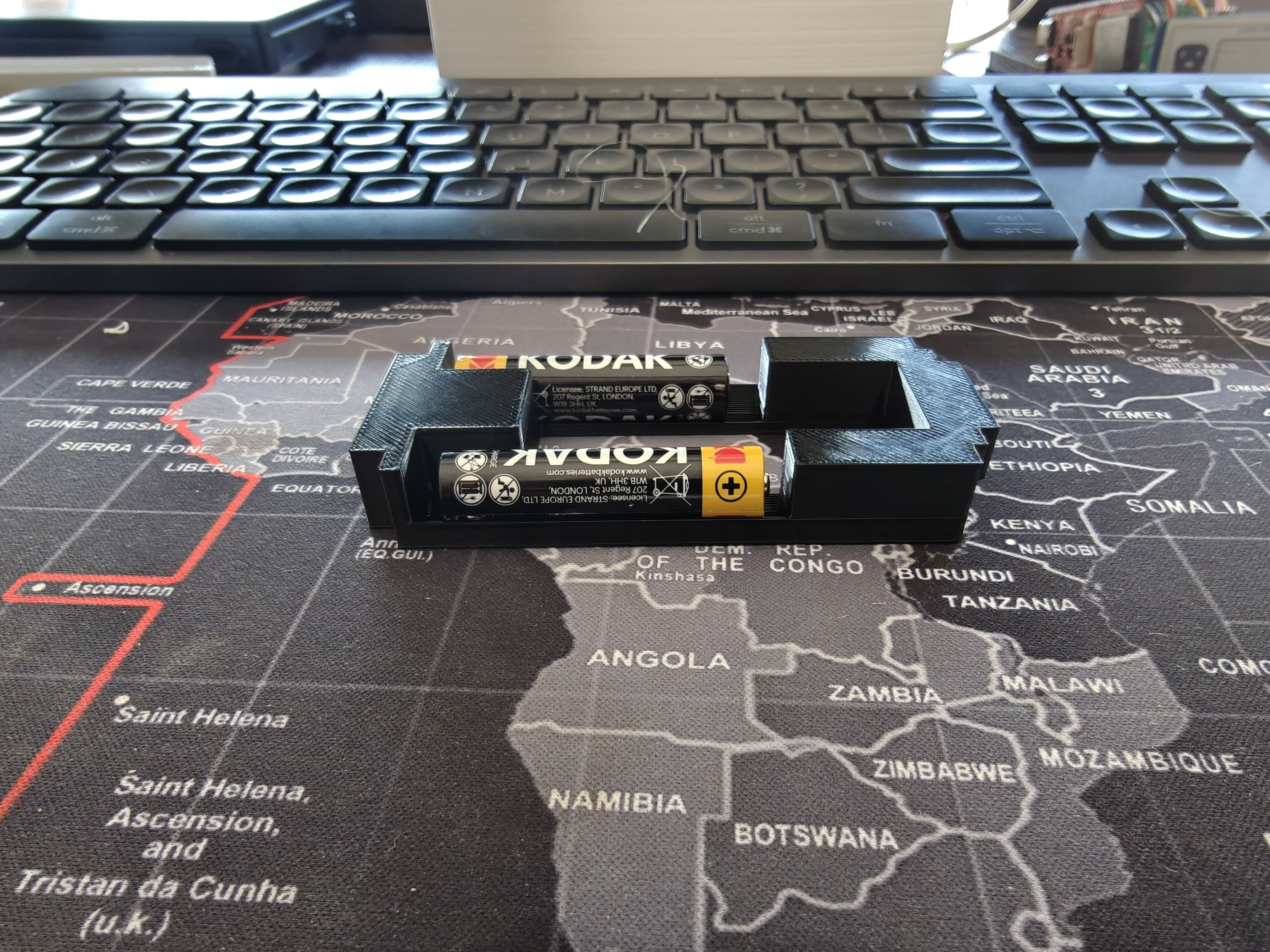
The assembled cradle + base plate stack is remarkably thin. The base plate's 7 mm height plus the cradle's 5.1 mm plug below the cover mating plane gives a total sub-cover height of just 12.1 mm.
Why a cradle insert instead of a base?
The 2-piece design (base-v3-2piece + cover) puts the cells, the Pico, and the Waveshare display all in the base. That works but the base ends up doing four jobs at once: holding cells, holding the Pico, supporting the display from below, and being the structural shell. Any change to one of those four roles ripples through the whole base.
Splitting it differently:
- Cradle insert — handles cell retention and Pico nesting. It's shaped like the cover's interior negative space, so it slides up into the cover from below. The two AAAs lie along X at the cover's ±Y long edges (cells flush with the long edges, cover/base inner walls catch them on the outside). The middle Y stripe is a through-cut where the Pico can nest up against the back of the Waveshare display.
- Base plate — closes the bottom and provides the snap retention. Four pegs at the cover's screw-bore positions slide up into the cover's blind M3 bores. A pocket on the base plate's top side receives the cradle's bottom 5.1 mm (the part that extends below the cover's mating plane).
This trades one big base for two smaller, single-purpose parts. Each can be re-printed independently — change the AAA bay shape without touching the bottom, change the bottom thickness without touching the cells.
Cradle geometry
The cradle is the negative space of top-cover-windowed-screen-inlay-v3-2piece's interior:
| Feature | Value (mm) |
|---|---|
| Outer footprint (matches cover cavity) | 86.7 × 41.4 |
| Total Z height | 12.1 |
| Plug top Z (= cover face-plate bottom = "screen face plane") | 7 |
| Plug bottom Z (5.1 below cover mating plane) | -5.1 |
| AAA cell ⌀ + slop | 11.1 |
| AAA cell length + slop | 49.5 |
| -Y bay center Y | 7.85 (cell flush with -Y long edge) |
| +Y bay center Y | 38.15 (cell flush with +Y long edge) |
| Cell axis | along X |
| Pico nest cutout | X = 6.3 → 48.1, Y = 12.1 → 33.9, full Z |
| FPC ribbon gap | X = 3.3 → 6.3, full Y, full Z |
| Connecting block (-X end of Pico nest) | X = 3.3 → 12.8, Y = 12.1 → 33.9, Z = -2.1 → 7 |
The connecting block was the design move that took the longest to land. The Pico nest is a through-cut; the -X end of it would otherwise be an open hole all the way down. The connecting block fills that -X end from the cradle's top down to Z = -2.1, leaving a 3 mm pass-through underneath at the very bottom for cable routing. It also gives the -X end of the cradle some structural mass.
The cells drop into the bays from above — the top half of each cylinder bay's bounding box is cut off so the cell can be placed straight in instead of slid in end-on. The cover's inside walls and the cradle bay's bottom half together hold the cell.
Base plate
The base plate is deliberately minimal:
| Parameter | Value (mm) |
|---|---|
| Outer footprint | 91.5 × 46 (flush with cover) |
| Total Z height | 7 |
| Outer corner radius | 4 (matches cover) |
| Outer bottom-edge fillet | 2 |
| Cradle pocket | X = 3.1 → 90.2, Y = 2.1 → 43.9, Z = 1.7 → 7 (5.3 deep) |
| Floor below pocket | 1.7 |
| Peg ⌀ | 3.0 (slip fit in cover's 3.2 M3 bore) |
| Peg height above plate top | 4.0 |
| Peg total length (from pocket floor) | 9.3 |
| Peg tip chamfer | 0.4 (self-guides into bore) |
The pegs rise from the pocket floor rather than the plate top. That matters: at the peg XY positions (the cover's screw-bore centers at the four enclosure corners), the pocket cuts away the plate's top surface, so a peg starting at the top would be a floating rod. Starting at the pocket floor — 1.7 mm above the plate's underside — makes each peg an integral column that runs continuously from the plate body, up through where the cradle's corner pillar cutouts are, and into the cover's blind M3 bore above.
Stack-up (global Z)
Z = 0      Base plate bottom (curved fillet)
Z = 1.7    Pocket floor — cradle bottom rests here
Z = 7      Base plate top = cover mating bottom
           Pegs continue past this point, into cover bores
Z = 11     Peg tips (4 mm into cover M3 bores)
Z = 14     Cover face-plate bottom = cradle top = display back plane
Z = 25.7   Cover top (bullnose peak, v3-2piece cover)
Total enclosure height: 7 (base plate) + 11.7 (cover) = 18.7 mm. The cradle extends across the seam — its top 7 mm sit inside the cover, its bottom 5.1 mm sit inside the base plate.
Print orientation
Both parts print with their broad flat surface on the bed:
- Base plate: pocket-side up (pegs printing as pillars). No supports needed; pegs are tall enough that the slicer drops a tiny brim under each — let it.
- Cradle: top side up (the AAA bay openings facing up). The half-cylinder bay troughs print as wide overhangs near the bay equator — fan to 80% in the bay region helps. No supports.
Both are small enough to fit two or three at once on a Bambu A1 Mini bed if you're iterating.
What's still open
- Cell contacts. No spring-contact slots are cut yet. The plan is two T-shape or leaf-spring contacts per cell, soldered to wires that exit through the FPC gap on the -X end of the cradle. Slot dimensions can be added once a contact is picked.
- Snap retention strength. The peg-into-bore fit is currently a 0.2 mm slip, not a real snap. If the assembled stack rattles, the easy fix is to bump peg ⌀ from 3.0 → 3.2 mm (interference fit), or to add a small barb at the tip.
- Cradle ↔ display alignment. The cradle's top is at Z = 7 cover-local, which is exactly where the cover's face-plate bottom is. With the inlay recess carved 3 mm up from there, the display sits 3 mm above the cradle top. There's no contact between cradle and display — the cover's inlay holds the display, the cradle holds the cells and Pico. If the Pico tries to wobble, that's the symptom that says the Pico nest cutout needs a foam pad or a printed pad on the base plate's pocket floor.
Files
04-24-designs-alterations/aaa-cradle-insert-v1.scad— the cradle04-24-designs-alterations/base-plate-v1.scad— the base platefreecad-export/— STEP, FCStd, and CSG copies of the v3-2piece cover family for non-OpenSCAD editing, plus full-dimensions blueprints and a FreeCAD modification guide