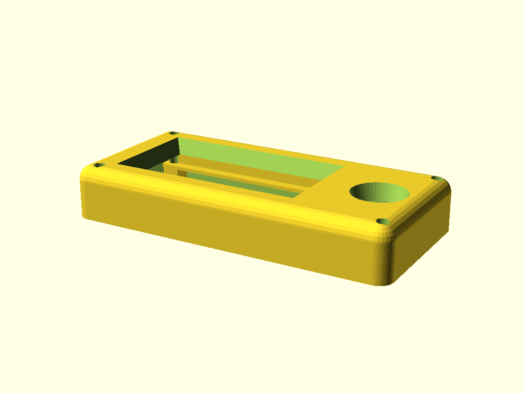
Rev 2 Top Cover — Windowed, Bullnosed, Tapered
The companion top piece to the Rev 2 "extended with joystick" base. Outer footprint 91.5 × 44mm matches base-v1 and middle-platform-v1 so the M3 through-bolts line up through the full stack. It combines two Rev 1 patterns — a curved bullnose top from top-cover-v3-rounded-top and a display slide-in housing with ±Y snap rails from top-plate-windowed-v1 — plus a new tapered joystick through-hole on the +X half of the face plate.
Two patterns worth lifting
The Rev 1 enclosure family had exactly one curved-top cover variant (top-cover-v3-rounded-top) and exactly one snap-rail display plate (top-plate-windowed-v1). Both earned their keep. For Rev 2 the natural move was to fuse them into a single cover piece — curved outside, rail-retained display inside, joystick hole where the board has space for it.
The bullnose, bigger
The original top-cover-v3-rounded-top used a 2mm bullnose radius — enough to soften the edge but not enough to define the top face. For this cover I pushed the radius to 4mm. At that size the curve reads from outside as a rolled edge across the whole front face, not just a corner fillet.

Thin face plate, tapered openings
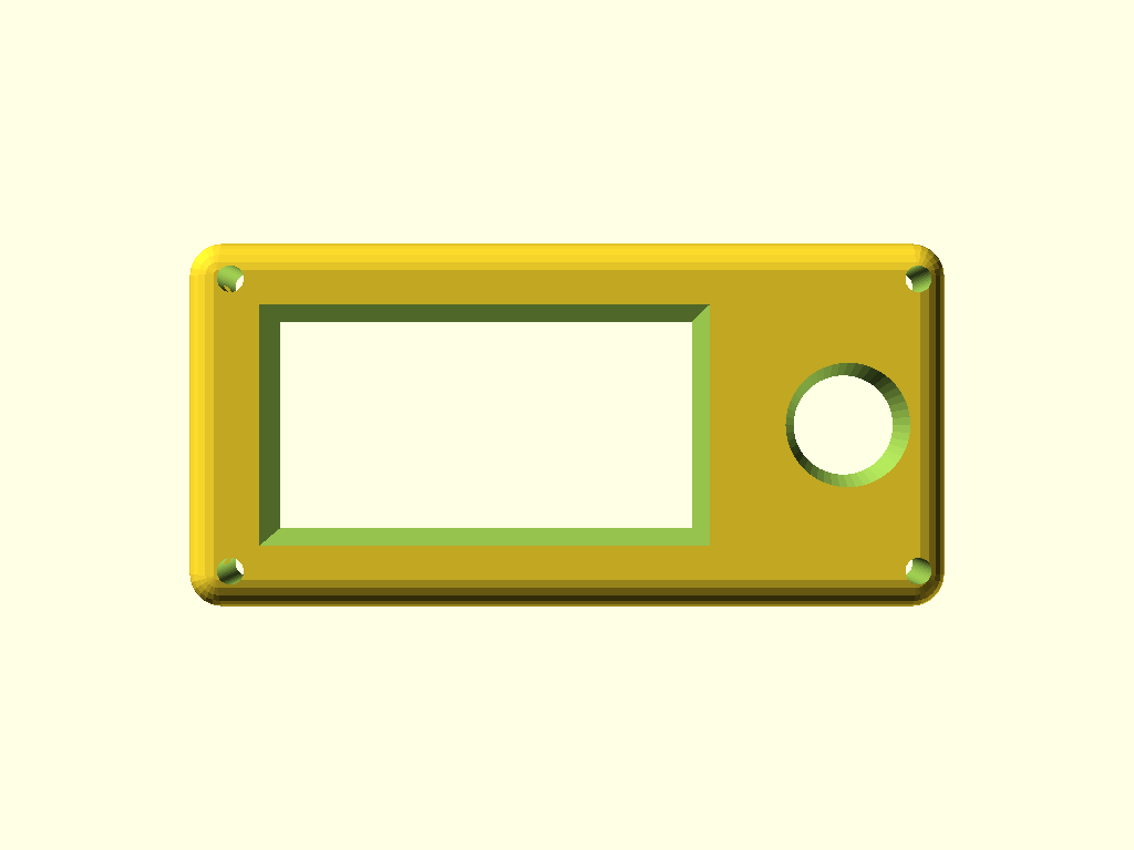
The face plate itself is 0.5mm — minimum printable thickness for FDM. That's enough to be a cosmetic bezel and not much more. The visible "top-face taper" isn't in the plate; it's in how the two openings get cut through the bullnose above.
Both openings use the same hull() trick:
- Bottom slab: true opening size at the face-plate bottom.
- Top slab:
(opening + 2·taper)at the very top of the cover. - The hull fills a frustum between them.
That frustum is what carves the bullnose into a shallow funnel around each opening. The material visibly slopes down into the screen edges and into the joystick hole, instead of meeting them at a hard square edge.
- Display window: 50 × 25 at the face-plate bottom → 54 × 29 at the cover top (2mm taper per side).
- Joystick hole: Ø12mm at the face-plate bottom → Ø15mm at the cover top (1.5mm taper on radius).
Rails, lips, and a wire gap
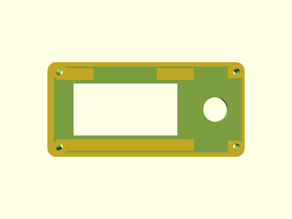
The display (Waveshare 2.13", landscape for Rev 2 — 65 × 30 with the 65mm side along X) slides in from below. Two snap rails hang off the face-plate underside along the display's ±Y edges, with a 1mm-thick inward-protruding lip at the bottom that catches the display once it's pressed past it.
Dimensions worth noting:
- Rail width in Y: 2.5mm — same as Rev 1's
top-plate-windowed-v1. An earlier Rev 2 version filled the full wall-to-display gap (~4.5mm) for no structural reason; now the rail is explicit and the leftover space between rail and display acts as a wire-routing channel. - Lip protrusion past the display edge: 1mm on each side.
- Lip thickness: 1mm (a single printable layer).
- Rail depth below the face plate: 4.5mm.
And a wire pass-through gap notches the middle of the -Y rail — 30mm long along the rail axis, 6mm deep across it. The cut is z-bounded to rail + lip material only (doesn't touch the face plate above), so wires can cross the rail boundary without fighting the snap. Rev 1 had the same notch in its portrait layout; this is the same pattern rotated for landscape.
-X pillars, only where they meet the base
The four M3 corner pillars align with the base and middle-platform pillars. Two of them — the -X pair, battery-side — intersect the rail's -X end. Leaving the full square pillar running from the base up to the face plate made that corner look cluttered from inside the cavity, because the rail sat stacked on top of a thick square post all the way up.
The fix: preserve each pillar's square column only up to its own top Z.
- -X pillars (battery end): preserved up to
rail_bottom_z = 5.5mm. The square pillar is only visible where it meets the base. Above that, the rail carries the bolt path, the face plate continues above the rail, and the bullnose caps it. - +X pillars (USB-C end): preserved up to the face plate bottom (no rails reach them, so the full column stays).
The bolt still has a continuous material path from the base to the top — pillar, then rail, then face plate, then bullnose. It just isn't a square post the whole way.
An earlier attempt at this fix added a separate "extra cut" after the cavity carve. That worked geometrically but shared a surface with the cavity carve at z = face_plate_bottom_z_mm, and the coplanar operand surfaces rendered as a ghost sliver under CGAL. Inlining the logic — one difference() block, per-pillar preservation height baked in — dropped the facet count and killed the sliver.
What's next
- Real print + fit-check against the actual Waveshare 2.13" and the joystick module. The 0.5mm face plate is at the printability floor, and the lip/rail geometry is only worth something if the display clicks into it the way the numbers say.
- Tune the joystick Ø once the exact thumb-joystick part is on hand — 12mm is a reasonable placeholder, not a measurement.
- Wire routing: confirm the 30×6mm gap is enough to pull the display ribbon + joystick cable through without binding.
Full design plan — dimensions, Z layout, and all the geometry patterns documented above — lives next to the SCAD at hardware-design/scad Parts/Rev 2 extended with joystick/design-plan.md.