Screen-Inlay Top Cover — First Print and Three Fixes
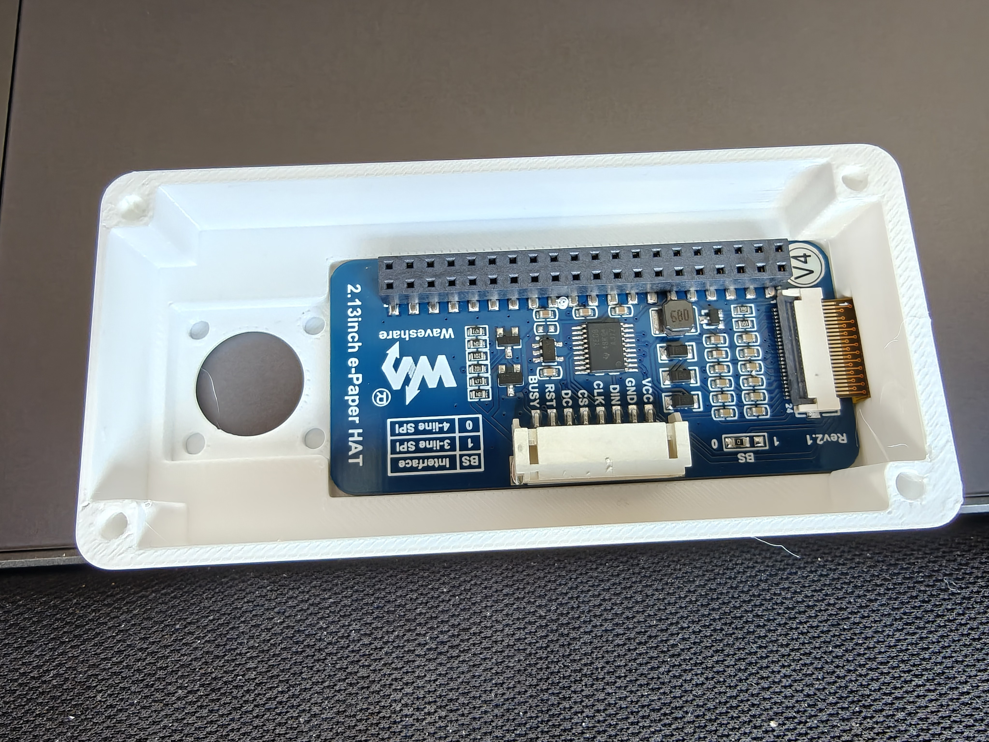
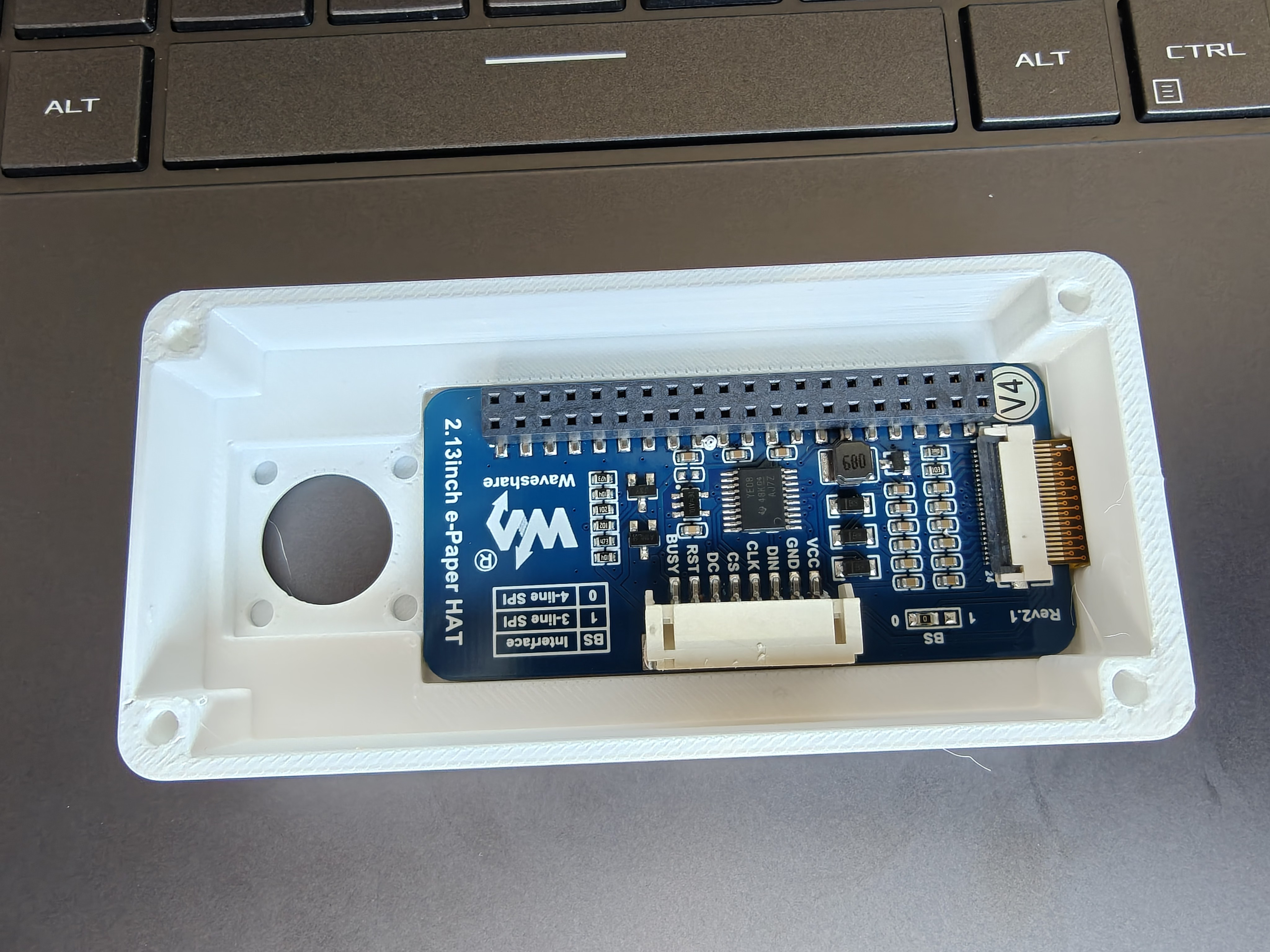
The screen-inlay top cover went to the printer overnight. It came out well enough to hold the raw Waveshare 2.13" module in its recess, but three things needed fixing before the next print. Each one is a small SCAD edit; together they move the part from "roughly right" to "match the actual hardware."
Why the inlay variant in the first place
The windowed-v1 cover from the earlier session used snap rails and lips to hold the Waveshare display from below — same pattern as Rev 1's top-plate-windowed-v1. That works with the display's stock carrier housing, where the PCB sits inside a plastic frame that gives the snap lips something to bite.
The raw Waveshare module — glass + FPC + nothing else — doesn't have that frame. The snap pattern doesn't translate. So the inlay variant drops the rails entirely, carves a 3 mm recess up into the face plate from below, and lets the module rest flat in the recess. A separate retention plate (bolting up through the four corner M3 pillars from below) handles holding.
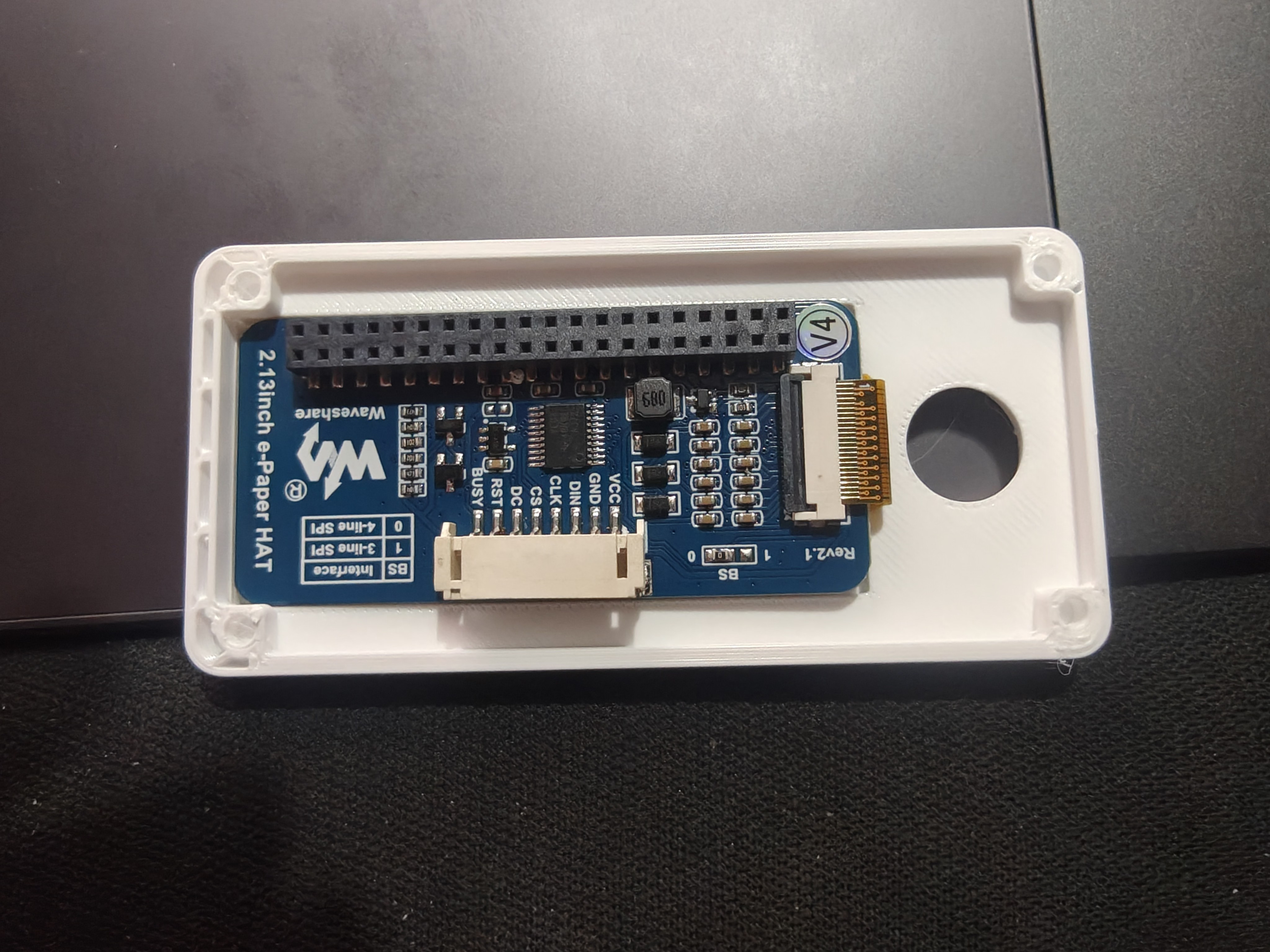
The FPC exits the +X end of the display and needs somewhere to go. A 13 mm-wide Y band on the -X end wall thins from the normal 3 mm down to 1 mm, directly opposite the joystick hole, giving the ribbon room to fold around the display edge and drop into the cavity below.
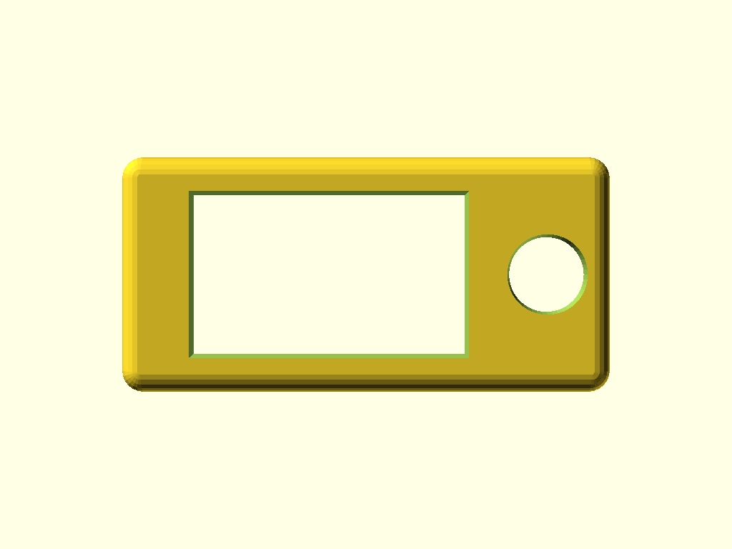
Fix 1 — the seam along the inlay's top edge
Here's the first issue, visible along the top edge of the inlay recess:
The face plate was 0.5 mm thick. That's one perimeter plus one thin top-skin layer. The slicer printed it, but the top-skin layer didn't fully close — probably because the geometry right above the inlay recess is a weird overhang/bridging situation, and a single thin top skin doesn't have enough material to fuse cleanly.
Fix: face_plate_thickness_z_mm bumped 0.5 → 0.7 mm. Two perimeters now, or one perimeter + two thin top layers depending on the slicer settings, which gives the top skin enough material to close even across the inlay bridge.
The 0.2 mm added to the face plate gets added to everything above — the cover total height for the inlay variant goes from 16.5 → 16.7 mm. Ignorable for the stack math.
Fix 2 — the ring of dimples around the joystick cutout
The v1 inlay had a 20 × 20 mm joystick-PCB pocket under the joystick hole, with four 3.2 mm blind mount bores at the corners for attaching a custom PCB. Those bores showed up in the print as four small dimples in a ring around the joystick cutout, on the underside.
Problem: the retention strategy for the joystick PCB is still undecided — glue, press-fit, and heat-set inserts are all on the table, and each wants a different bore geometry (or no bores at all). Printing four clearance holes and then having to ignore them or fill them was going to hurt more than it helped.
Fix: the four bores were removed from both inlay variants. The parameter definitions (joystick_pcb_mount_bore_*, joystick_pcb_mount_bore_xy_positions_list) are intentionally kept so the geometry is one block away from returning — a single for loop inside the module's difference() brings them back whenever the retention plan is locked in.
Fix 3 — the window doesn't match the actual viewable pixel area
The window was 50 × 25 mm centered on the display with a 2 mm +X shift toward the joystick (asymmetric bezel, more material on the battery side). That was sized from the Waveshare datasheet. The actual viewable pixel area on the physical module doesn't quite match the datasheet:
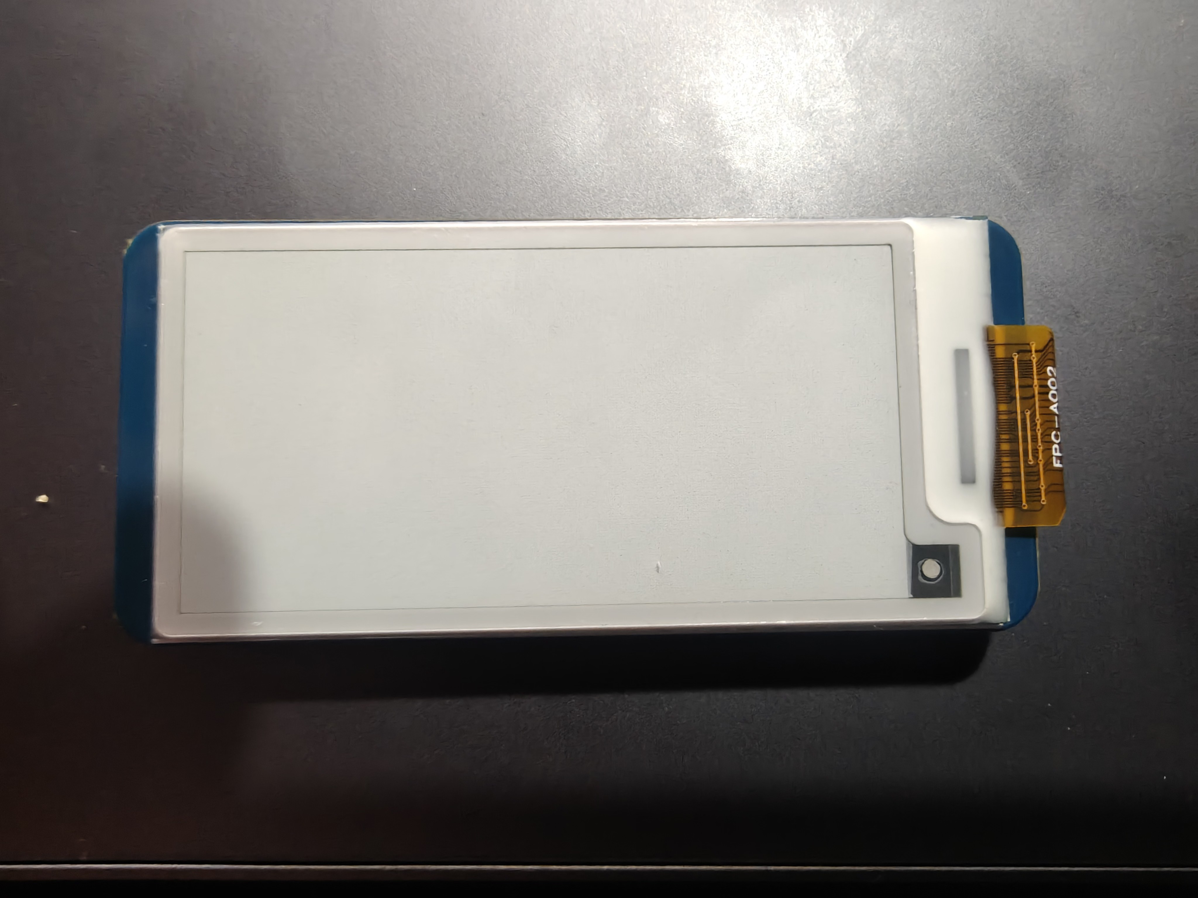
Comparing the print against the module, the window was:
- 2 mm too long in X on the -X end (the -X short side cut past the viewable pixels into dead bezel).
- 2 mm too short in Y overall (the top and bottom long sides cut into the viewable pixels at the ±Y edges).
Fix (applied to all three cover variants for consistency — both inlay variants and the base top-cover-windowed-v1.scad):
| Parameter | Was | Now | Effect |
|---|---|---|---|
display_viewing_window_length_along_x_mm |
50 | 48 | -X short side moves inward 2 mm |
display_viewing_window_depth_along_y_mm |
25 | 27 | ±Y long sides each extend 1 mm outward |
display_window_shift_toward_joystick_x_mm |
2 | 3 | compensates for the 2 mm length reduction so only the -X edge shifts — the +X edge stays at X=62.9 |
New window: X 14.9 → 62.9, Y 8.5 → 35.5. -X bezel grows from 9.5 → 11.5 mm (more material on the battery side), ±Y bezels shrink from 2.5 → 1.5 mm each. The +X bezel (5.5 mm) and the joystick hole stay put.
Second print
Second print slices next. If the seam is gone, the dimples are gone, and the viewable pixel area lands cleanly inside the window, the inlay cover is ready for assembly against the full stack. If not — the three fixes each point at specific parameters that can keep iterating.
Source updated in:
top-cover-windowed-screen-inlay-v1.scad— 3 mm FPC divet varianttop-cover-windowed-screen-inlay-v1-2mm.scad— 2 mm FPC divet siblingtop-cover-windowed-v1.scad— window dims synced for consistency
Full dimensions reference (every parameter, every part in the Rev 2 folder) lives at rev2-models-dimensions.md.