Dual 10440 Cells, Case Redesign, and a 2-Piece Stack
The screen inlay was dialed in. Next problem: the 3000 mAh LiPo pouch the case was originally sized for doesn't actually fit in the Rev 2 cavity. A photo study, a chemistry comparison, four base variants, and a 2-piece restructure later, the stack is 11 mm thinner and the cells can be slid in from outside without popping the cover.
The fit problem
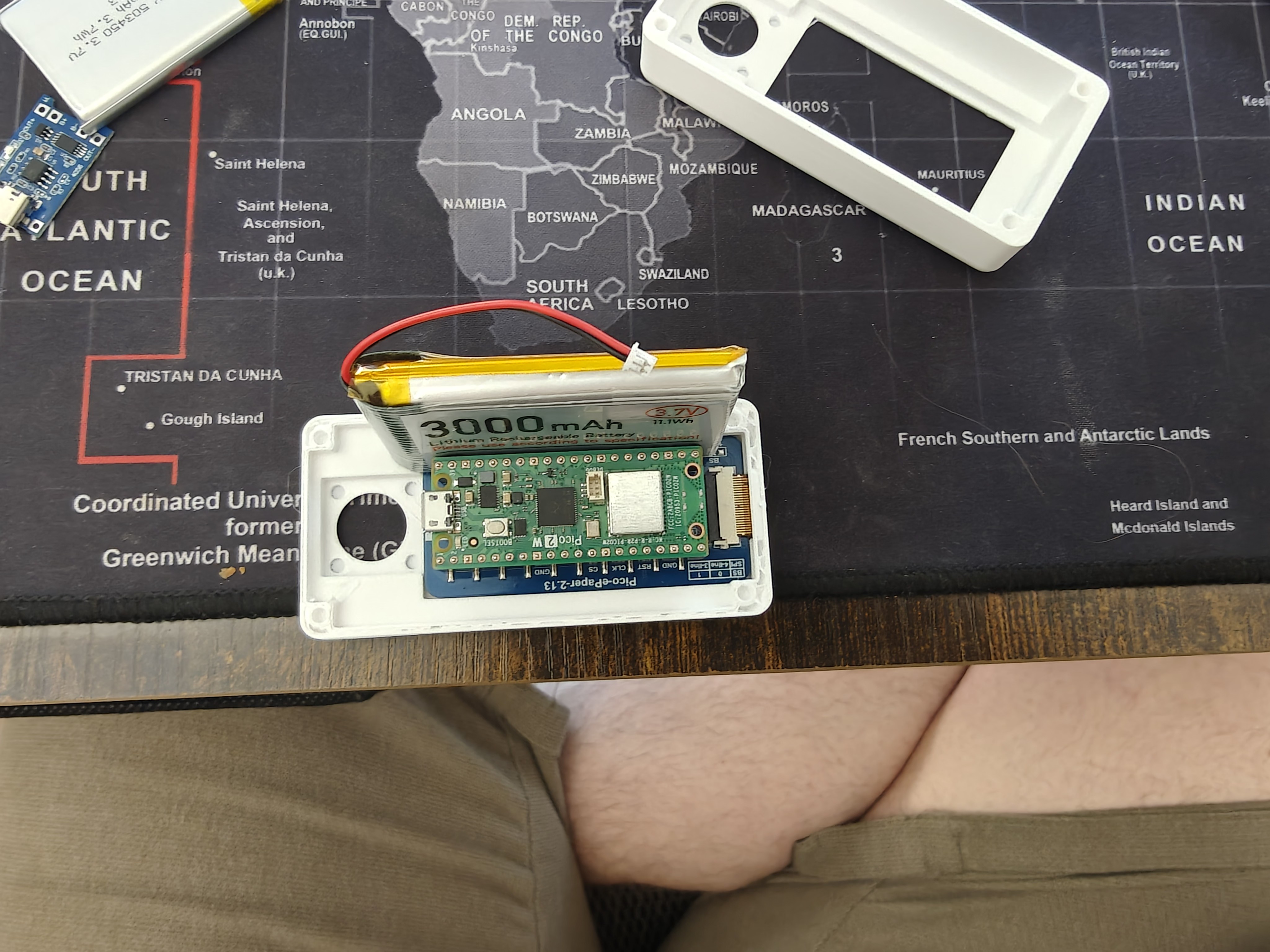
The 3000 mAh pouch is roughly 60 × 35 × 10 mm. The Rev 2 base inner cavity is ~87 × 40 × stack. The cell overhangs the ±Y long walls by ~5 mm. It can't sit inside the case at all — it has to stack above the Pico W, which burns ~10 mm of stack height the enclosure doesn't have.
The fix: drop the one-big-cell strategy and go with two thinner cells flanking the board.
Chemistry matters more than form factor
The initial photo fit-check used 2× Kodak Xtralife alkaline AAAs because they're what was on the desk:
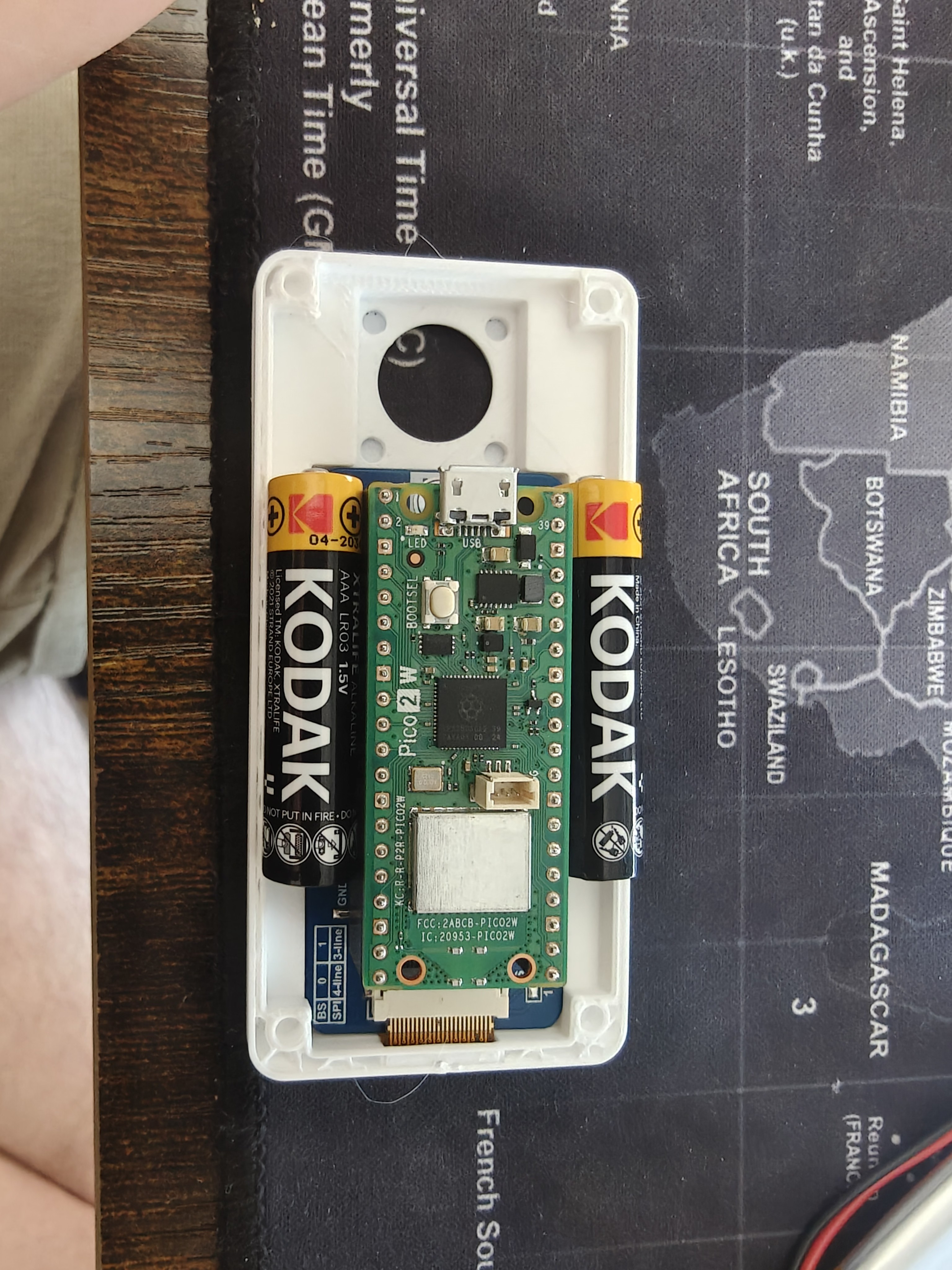
The cells fit. But alkaline AAAs are a terrible choice here:
- 1.5 V per cell. Two in series gives 3.0 V fresh, drops to ~2.0 V near end of life — brownouts against the Pico W's 1.8 V VSYS minimum. Two in parallel gives 1.5 V — doesn't meet VSYS at all.
- Not rechargeable. The existing TP4056 USB-C charge board is Li-ion only; alkaline chemistry would need to come out of the case and get thrown away.
- High internal resistance. Pico W's WiFi TX peaks (~250 mA bursts) sag alkaline pack voltage hard, especially as the cells age.
The drop-in fix is 10440 Li-ion — same exterior dimensions as an AAA (Ø 10 × 44 mm), but 3.7 V per cell, same chemistry as the existing LiPo pouches, and ~350 mAh each. Two in parallel gives a ~700 mAh pack at 3.7 V, charges with the unchanged TP4056 (just swap R_prog from 1.2 kΩ → ~3.4 kΩ to derate the charge current to 350 mA CC), and feeds the Pico W's VSYS directly.
The wiring rule — and it's a real one: same model, same batch, match voltages within 0.1 V before connecting + to + and − to −, each cell with its own PCM. Mismatched parallel cells dump current into each other.
Four base variants in one afternoon
All of these landed under hardware-design/scad Parts/Rev 2 extended with joystick/04-24-designs-alterations/:
base-v2-thin-dual-10440 — first cut
Minimum change to fit the new cell chemistry into the existing 3-piece stack: bump outer Y from 44 → 46 mm (so two Ø 10 mm cells + 21 mm Pico W + slop actually fits), drop total Z from 14 → 12 mm (cell fills the bay height exactly), thin the floor from 3 → 2 mm, collapse from two USB-C cutouts to one (Pico W has a single port), and add 4 generic contact-tab slots for stamped strip contacts at each cell bay's ±X ends.
Matching forks: middle-platform-v2-46y and top-cover-windowed-screen-inlay-v2-46y — same content as v1 but +2 mm Y so the full stack bolts up.
base-v3-2piece — merge the middle platform into the base
Next ask: "I don't want a middle platform, I want this done in 2 pieces — have the base extend up and inlay into the Pico and secure the back of the Waveshare."
Done. The base now extends up to z=14 and absorbs the role the middle platform used to play. The Pico W drops into the centered chamber at Y=12.1–33.9 (the "inlay"), and the Waveshare display's ±Y edges overhang the 21.8 mm Pico chamber by ~4 mm on each side — those overhangs rest on the solid base rim at z=14. Top cover presses down from above. Display's trapped between.
Matching cover: top-cover-windowed-screen-inlay-v3-2piece drops the 5 mm middle-platform pedestal reservation that used to sit at the cover's bottom, going from 16.7 mm → 11.7 mm. Stack total: 25.7 mm, down from 36.7 mm — 11 mm thinner.
base-v4-2piece-open — cells slide in from outside
v3's cells were trapped in sealed bays once the top cover was on. Fix: two rectangular slots cut through the -X end wall, one per cell bay, matching each bay's Y × Z cross-section. Cells slide in from outside before cover install; spring contacts at the -X end press them +X against the solid +X stop. (For a fully closed case, print a small battery-door clip that snaps onto the -X end over the slots.)
v4 also adds raised ±Y lips on the cell-bay ceiling at the Pico chamber boundary, protruding 1 mm above the case top into the cover's cavity on the non-battery edges. Stiffens the base-cover joint along the long edges without interfering with cell insertion.
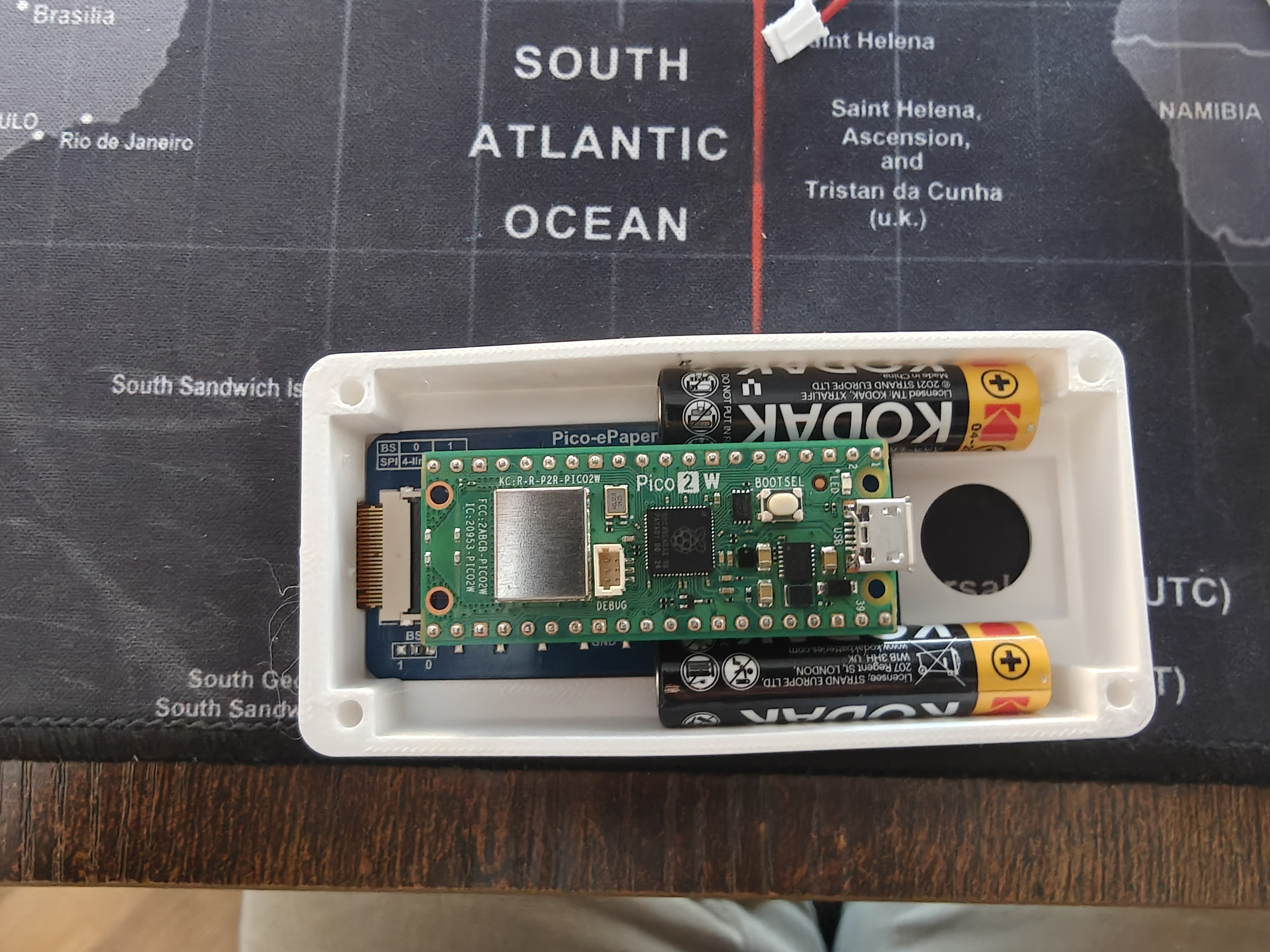
The final layout
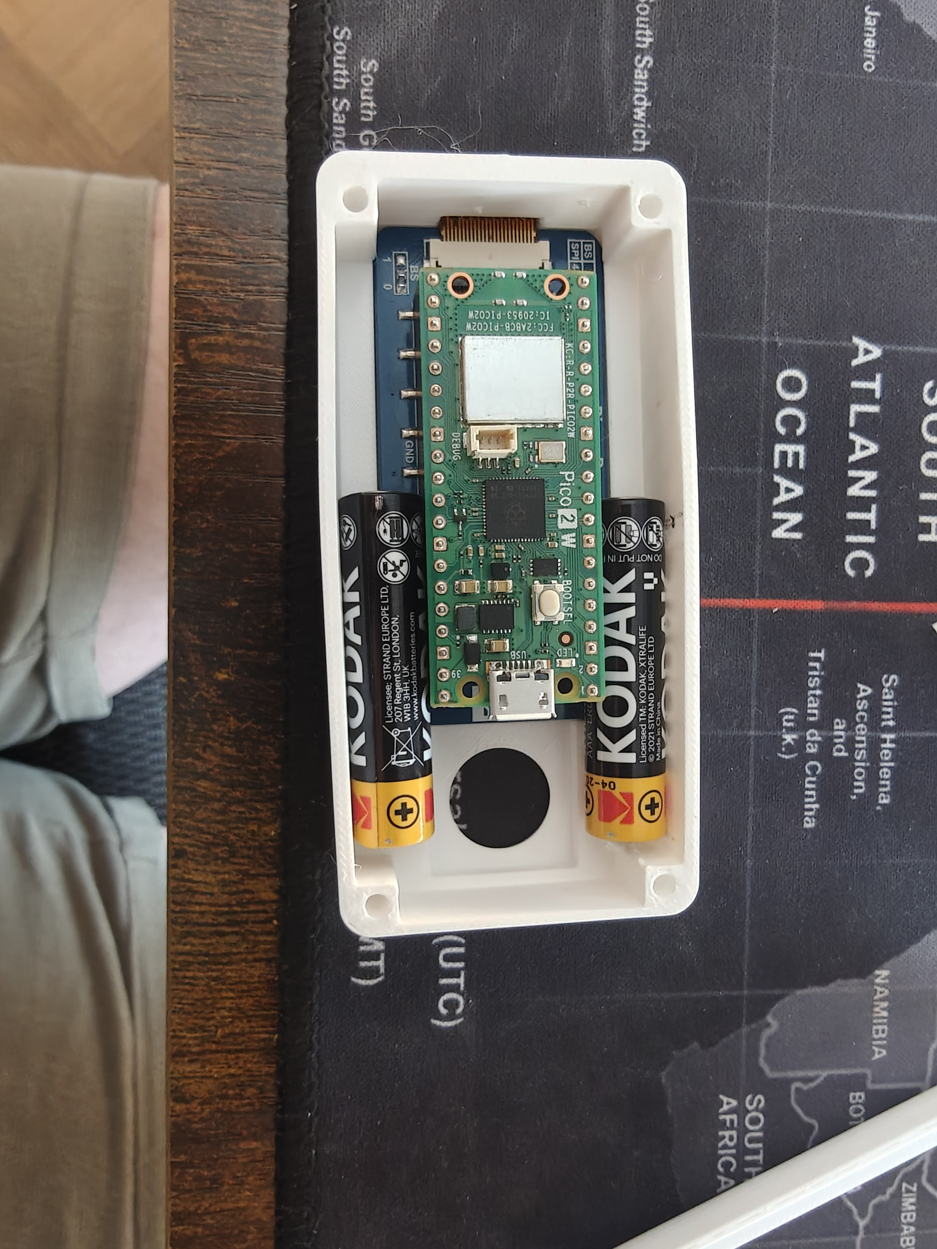
Pico 2 W in the middle, two cells along ±Y, FPC ribbon exiting at -X toward the Waveshare display (shown separately below), joystick hat at the +X USB end.
What didn't work
A top-cover-v4-contoured-25mm.scad experiment tried to sculpt the cover's underside with downward extensions that wrapped around the cell tops, the FPC fold, and the Pico chamber — hitting a 25 mm total stack by having the cover do more of the enclosing work. The user's response: "this is batshit awful delete it."
Fair. File's gone. The existing base-v4 + cover-v3-2piece combination hits 25.7 mm with a much simpler geometry.
What's next
- Print
base-v4-2piece-open.scad+top-cover-windowed-screen-inlay-v3-2piece.scadas the matched pair. - Order 2× 10440 Li-ion protected cells (AliExpress, ~$3–6 each) and matching stamped-strip battery contacts.
- Derate TP4056 R_prog to ~3.4 kΩ.
- Test cell insertion and battery-door strategy — either a small printed clip over the -X slots, or rely on the spring contacts + gravity.
Research docs: battery-redesign-shopping-list.md, solar-charging-research.md.