Rev 2 "Extended with Joystick" — a Purpose-Built Base
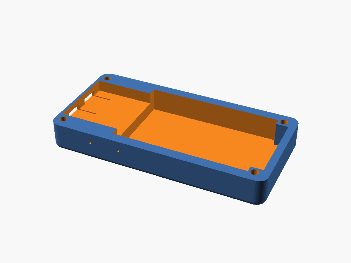
Parallel track to the 5-piece sandwich enclosure: a standalone base designed around the extended-with-joystick layout. Battery sits flat on the left half, the ESP32 board stack sits on the right and overhangs the battery top by 2mm, two USB-C ports punch out the +X wall, and the whole thing drops into four M3 corner pillars.
Why a new base
The existing sandwich enclosure assumes a board-on-top / display-on-bottom stack. The joystick variant is a different shape problem: a lipo cell and an ESP32 dev board sitting side-by-side in a flatter footprint, with the board's USB-C ports breaking out one end and (eventually) a joystick breaking out the top.
Rather than parameterize the existing case into knots, I started a new file (base-v1.scad) with measurements read directly off a hand-drawn sketch, and converged on the geometry from there.
Layout at a glance
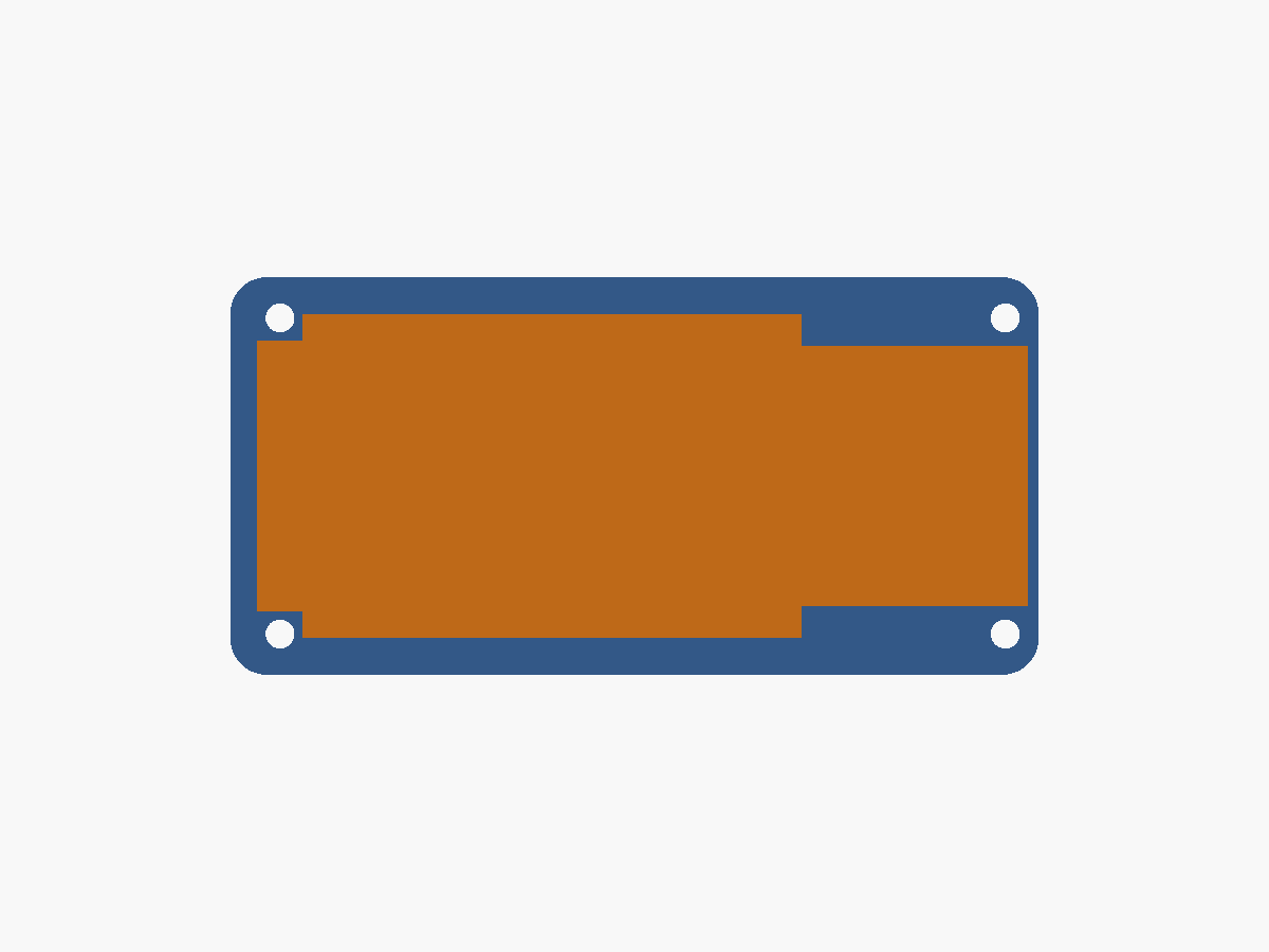
- Outer shell: 89.5 × 44 × 12mm (v1.2 trim after v1.1 resize), 4mm top-view corner radius, 2mm bottom fillet.
- Battery chamber on the left: inner 60.3 × 35.8mm to fit the (actual) cell with 0.4mm slop per side.
- ESP32 chamber on the right: inner 23 × 28.8mm on a 5mm raised shelf, narrower in Y than the battery so the step is visible in plan view.
- 2mm divider rib between the chambers (carries some of the board-left-edge load).
- Four 5×5mm M3 pillars in the corners, Ø3.2mm through-holes.
Asymmetric end walls
The ±X ends carry different loads:
- +X wall = 1.2mm (USB side). Thin enough that the two USB-C ports punch through a minimum of material, so a USB-C plug can seat fully without bottoming against the plastic.
- -X wall = 3.0mm (battery side). Thicker for strength and because there's no cutout on this end to weaken it.
- ±Y long walls = 2mm, project default.
The resulting outer corner radius is capped at 4mm — any bigger and the outer pillar corner at the USB end would have poked past the shell's rounded profile.
Dual USB-C cutouts
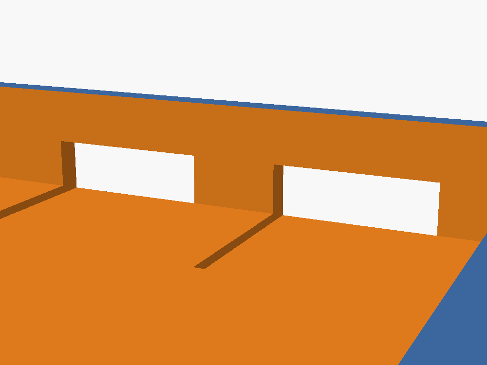
Two 7.8 × 2.8mm cutouts at Y=16mm and Y=28mm (symmetric about Y=22mm, 12mm apart). Height is the measured port body (2.6mm) plus a 0.2mm allowance so the PCB seats truly flat against the plastic. Z-center is at 8mm after the v1.3 bump — fully above the ESP32 shelf (z=7) so the port recess lives in clear chamber space.
Shelf divets for the USB shield tabs
Each USB-C receptacle has a small shield tab on its underside that hangs below the PCB. If the shelf is perfectly flat, the PCB sits 0.2mm proud of the shelf — enough to misalign each USB cutout vertically. Fix: a 0.2 × 8 × 7.8mm recess carved into the shelf top under each port. The divets stop at the inner face of the +X wall; an earlier version punched all the way through and rendered as a visible slit below each USB cutout.
Pillars that follow the fillet
Last fix before checking in: the corner pillars' outer bottom edges were flat right down to z=0, but the shell's bottom fillet (via a minkowski sphere sum) contracts the z=0 outline inward by the fillet radius. Result: each pillar's outer corner at z≈0 poked ~1.4mm past the shell outline, showing as a tiny plane popping off the curved front face.
Solution was trivial once identified — intersection() the union of all four pillars with the outer shell. The pillars now inherit the fillet curve at their bases and the front face is smooth.
v1.1 resize pass
A quick second pass dropped the base against a longer battery and a thinner overall profile:
- Outer X 82 → 96mm (+14 to fit a longer cell).
- Total height 22 → 12mm (-10, making the base much flatter).
- Battery cell length 52 → 66mm (chamber derived as cell + 2·slop → 66.8mm).
- Overhang shelf raised 2 → 5mm above the battery floor — battery "pit" under the ESP32 board is now 3mm deeper.
- USB-C cutout z-center 7 → 6mm (holes move down 1mm).
ESP32 chamber clear height drops from 18mm to 5mm as a consequence — tight but still enough for PCB (1.6mm) + USB-C receptacle body (2.6mm). If the real PCB's port body sits higher than the 6mm cutout, the mount strategy (board orientation, shelf height) gets a follow-up pass.
v1.2 battery trim
The v1.1 extension overshot — the cell actually on hand needed 6.5mm less length. A one-parameter-pair fix:
- Outer X 96 → 89.5mm (battery end only).
- Battery cell length 66 → 59.5mm (chamber → 60.3mm).
- ESP32 chamber inner length is untouched at 23mm — outer and battery each dropped by the same 6.5mm so the remainder for the ESP32 side falls out of the same equation.
v1.3 USB-C cutouts raised
Follow-up to v1.1's USB z-drop: with the shelf at z=7 and the cutout center at z=6, the cutouts straddled the shelf and the port recess had to carve through it. One-parameter fix:
- USB-C cutout z-center 6 → 8mm.
Cutout now spans z=6.6–9.4, fully above the shelf. With the PCB on the shelf (z=7), PCB top at 8.6, and a 2.6mm port body above it (z=8.6–11.2, center 9.9), the cutout still sits a bit low of the natural port-center position but now lives in clean chamber space instead of slicing through the shelf.
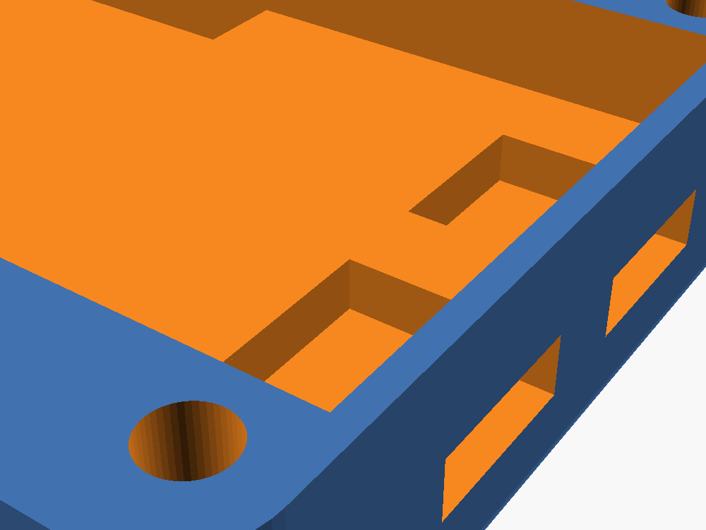
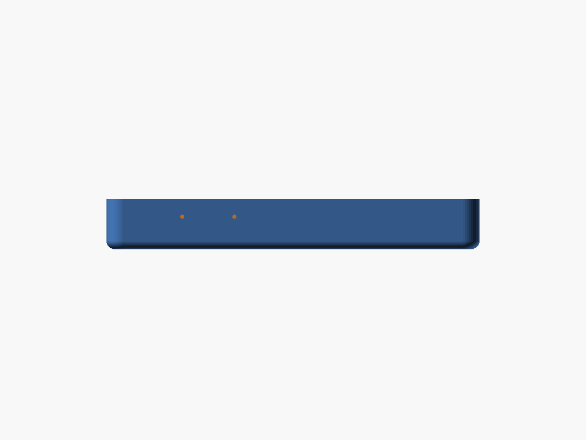
v1.4 BOOT / RESET paperclip poke-through holes
The board is mounted component-side down on the ESP32 shelf — buttons face the floor. So the paperclip access can't be a side-wall hole; it has to be a vertical hole in the base floor that the paperclip enters from underneath the enclosure.
Two Ø1mm vertical through-holes:
- Hole 1: (x=71.3, y=32.5), 17mm in from the +X inner wall face.
- Hole 2: (x=58.8, y=32.5), 12.5mm to the left of hole 1.
- Y = 32.5mm = 11.5mm in from the +Y outer edge (puts both holes inside the ESP32 chamber's Y range of 7.6–36.4).
The cylinder subtract runs the full enclosure height, so a single op carves the floor, the shelf-region material, and any chamber space above. Caveat worth noting: hole 2 at x=58.8 is just past the battery/ESP32 divider — if the real board's RESET sits over the ESP32 chamber (x ≥ 65.3), the cluster needs to shift or shrink.
What's next
This is the base only. Still to come in this branch:
- Middle plate sized for the 96 × 44 footprint (reusing the existing middle plate pattern but adjusted for this Y depth).
- Top cover with a joystick window and the USB-facing wire exit.
- Optional straps/anchors for the battery.
Full design plan (measurements, sketch photos, what's confirmed vs. still-to-confirm) lives next to the SCAD at hardware-design/scad Parts/Rev 2 extended with joystick/design-plan.md.