First Real Input — Joystick Wired, Octopus Responds
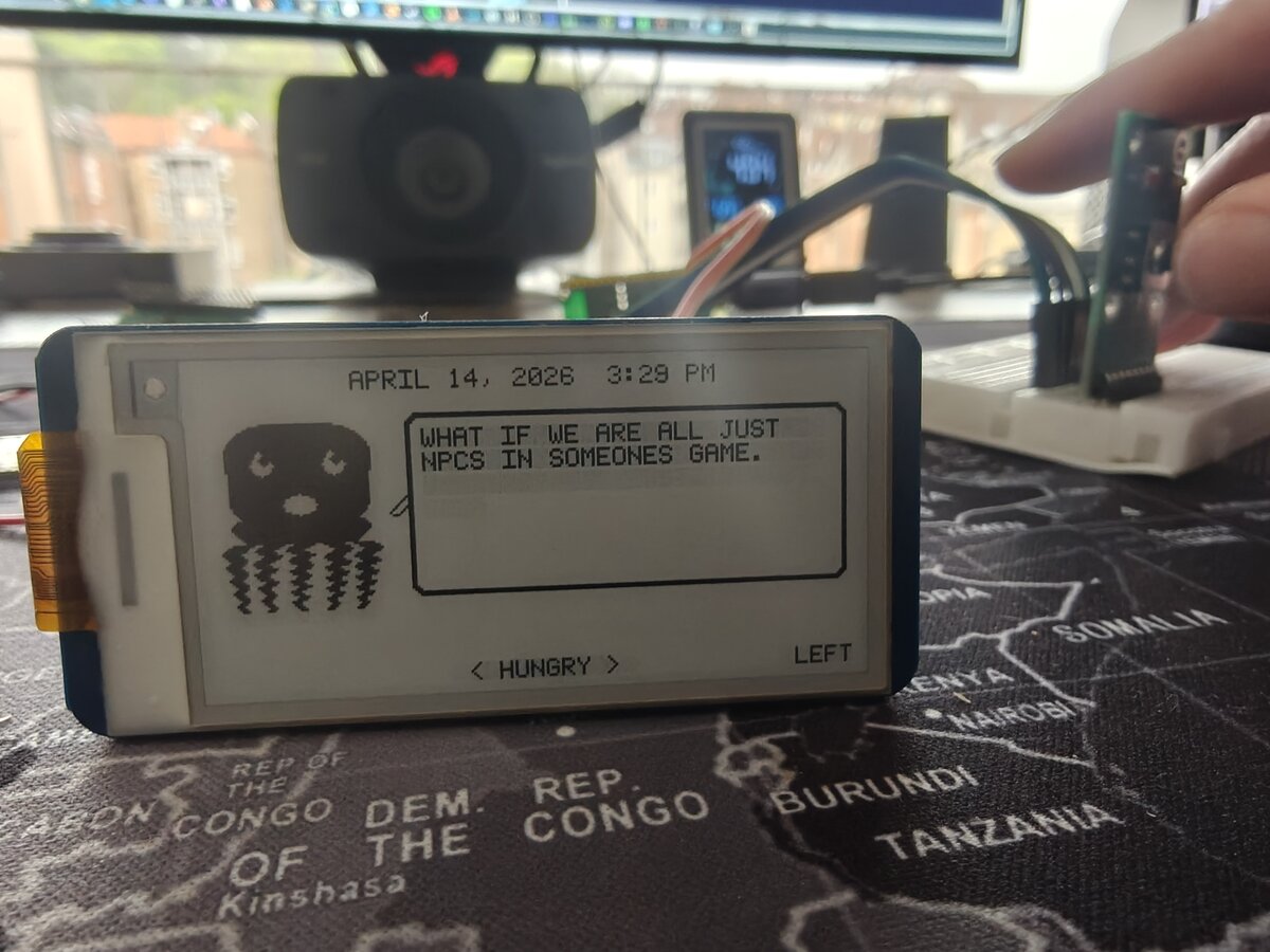
The octopus can finally hear us. For the first time, the Dilder responds to physical input — a 5-way joystick module wired to the Pico W's GPIO pins, driving mood changes on the e-ink display in real time.
The Build Session
Today was all about getting physical input working. Until now, the octopus was controlled entirely over serial USB — type a key, mood changes. Useful for development, but not exactly a handheld experience. Time to fix that.
Hardware Setup
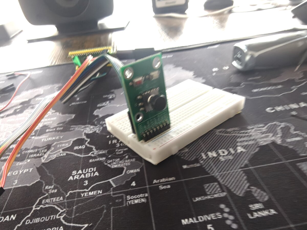
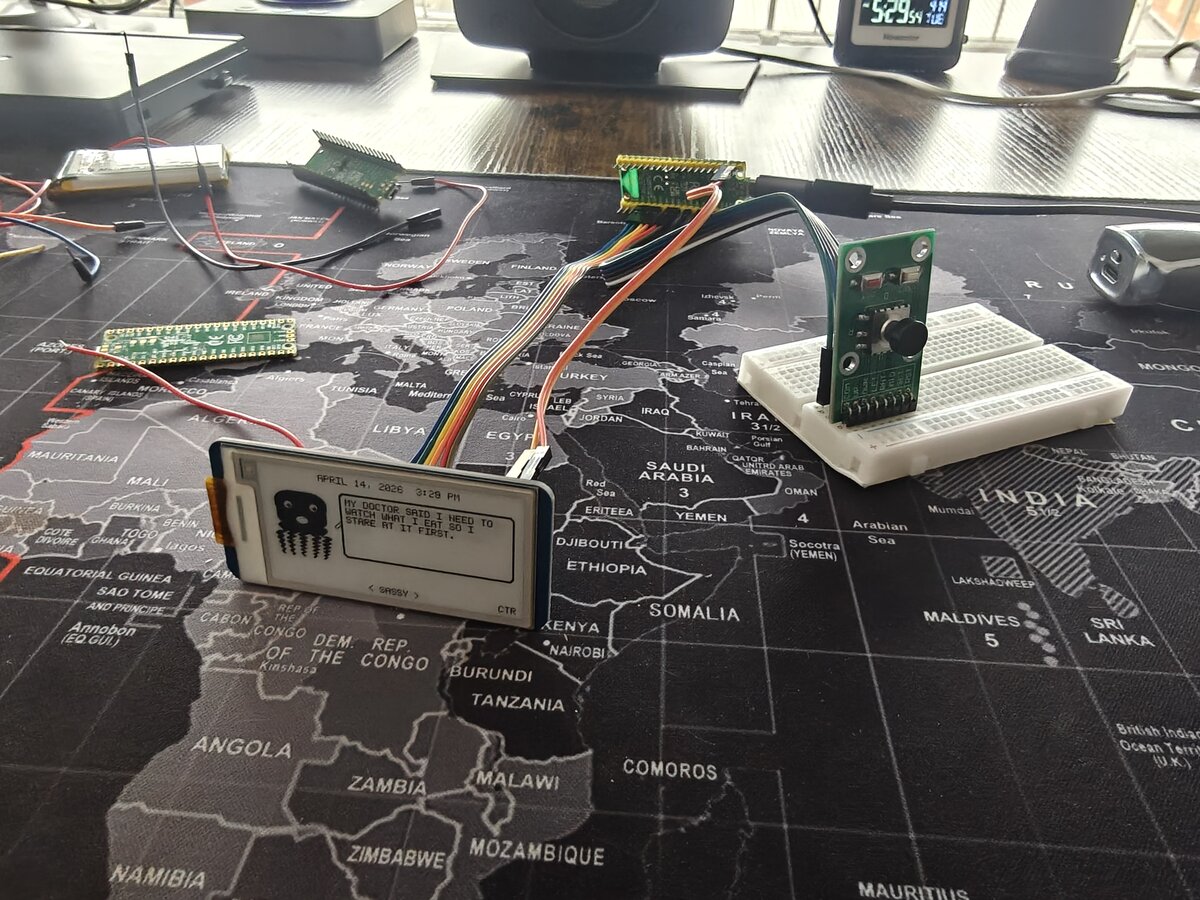
The test bench is coming together. The Pico W sits on a breadboard with the Waveshare Pico-ePaper-2.13 connected via jumper wires from the 8-pin breakout header, and the DollaTek 5-way joystick module plugged into the board alongside it.
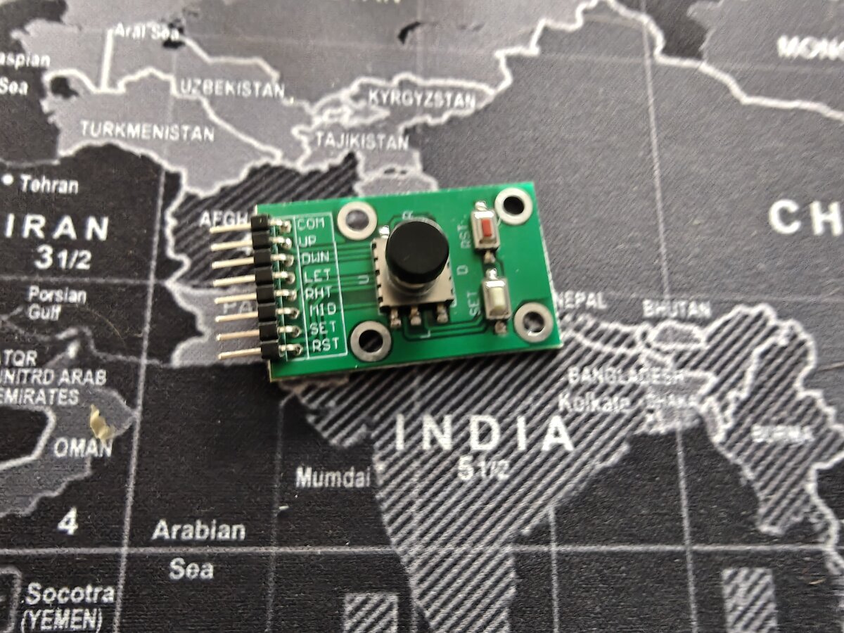
The joystick wiring is straightforward — five GPIO pins (GP2–GP6) with internal pull-ups, active LOW when pressed. COM goes to ground. No external resistors, no level shifting, just direct digital input.
The Firmware
The new Joystick Mood Selector builds on the existing mood-selector firmware:
- LEFT / RIGHT — cycle through all 16 moods
- UP — random mood
- DOWN — new random quote (same mood)
- CENTER — reset to SASSY
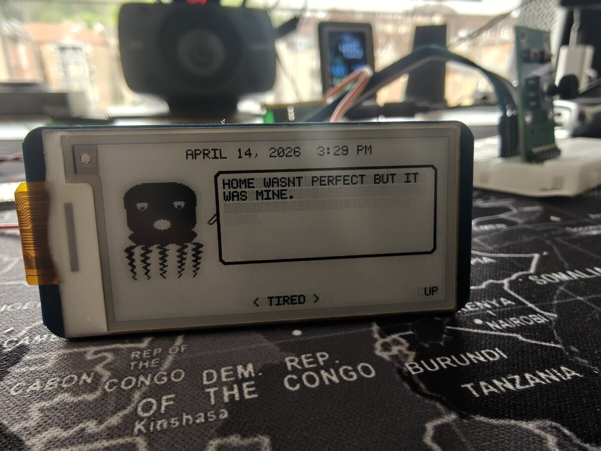
The last input pressed is shown on the right side of the status bar, so you can see exactly what the device registered.
The Wiring Mistake
One bug that wasn't in the code: the CENTER button didn't register at first. Turns out the wire was plugged into pin 8 (GND) instead of pin 9 (GP6) — they're right next to each other on the Pico W. Classic breadboard mixup. Moved the wire one row over, and center clicks worked immediately.
Lesson: when a single GPIO input doesn't work but others do, check the physical wiring before debugging the code.
Battery — Ready for Planning
The LiPo battery is also on the desk now — an InnCraft Energy 503450, 1000mAh, 3.7V with a Molex 1.25mm 2-pin connector.
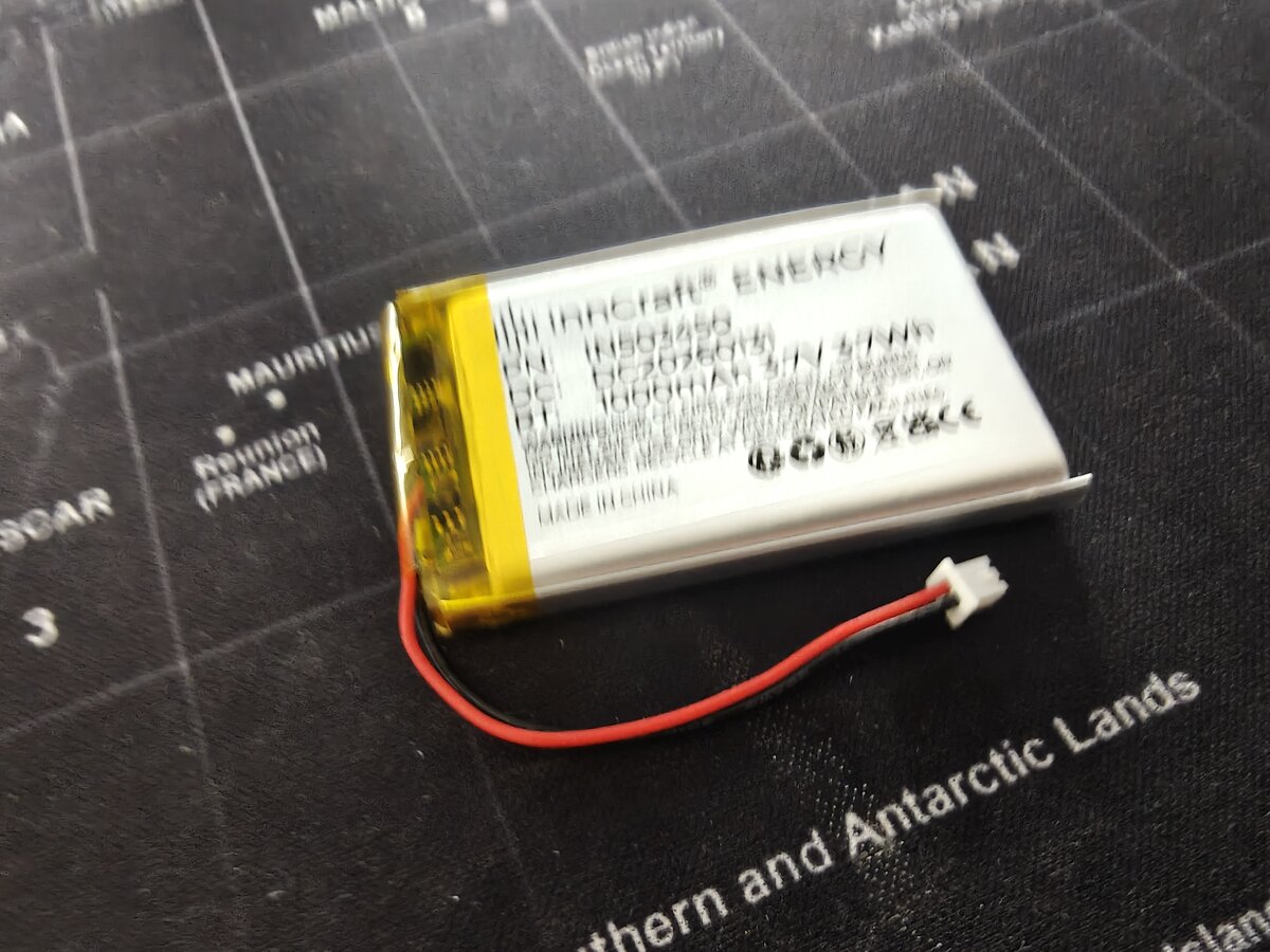
The Battery Wiring Guide is already written with three wiring options (direct, TP4056, PowerBoost). Next step: wire it up on the breadboard and test untethered operation. The Pico W's VSYS pin accepts 1.8–5.5V, and the LiPo's 3.0–4.2V range sits right in the middle — no boost converter needed.
Estimated battery life in Tamagotchi mode (10 min active, 50 min sleep per hour): ~6.8 days.
What's Next
- Wire the battery to VSYS and test untethered operation
- Add battery voltage monitoring (GPIO29 / ADC3 — already documented)
- Build a battery indicator for the e-ink display
- Wire and test the remaining peripherals (GPS, HC-SR04)
- Start building the game loop state machine
The octopus has eyes, a mouth, opinions, and now it can hear you push a button. We're getting closer to a real pet.